A vertical take-off and landing fixed-wing aircraft

A vertical lift, fixed-wing technology, applied in the field of aircraft, can solve the problems of increased resistance, large take-off and landing space, small lift, etc., to achieve the effects of improving stability, reducing resistance, and increasing power

Inactive Publication Date: 2019-01-25
FOSHAN SHENFENG AVIATION SCI & TECH
View PDF0 Cites 3 Cited by
  • Summary
  • Abstract
  • Description
  • Claims
  • Application Information

AI Technical Summary

Problems solved by technology

Among them, the rotorcraft mainly controls the rotation of the propeller structure to generate lift of different sizes so as to achieve the purpose of controlling the vertical take-off and landing of the rotorcraft in the vertical direction; however, there are obvious defects in the flight speed and stability of the rotorcraft.
The fixed-wing aircraft has greater flight speed and more stable long-distance flight capability than the rotary-wing aircraft; however, the take-off and landing operations of the fixed-wing aircraft need to be realized through the taxi runway, which takes up a large space for take-off and landing. As a result, the use conditions of fixed-wing aircraft are limited, and it cannot complete take-off and landing operations in a small space
[0003] In order to solve the above problems, more and more people turn the research direction to the fixed-wing aircraft of vertical take-off and landing, but the fixed-wing aircraft capable of vertical take-off and landing in the prior art has the following obvious defects: on the one hand, the The lift force is small, it is difficult to complete the stable vertical lift process and hovering flight; on the other hand, the small rotor will increase the resistance during the flight process during the stable flight process, resulting in unnecessary energy consumption

Method used


Image

  • A vertical take-off and landing fixed-wing aircraft
  • A vertical take-off and landing fixed-wing aircraft
  • A vertical take-off and landing fixed-wing aircraft

Examples


Embodiment 1

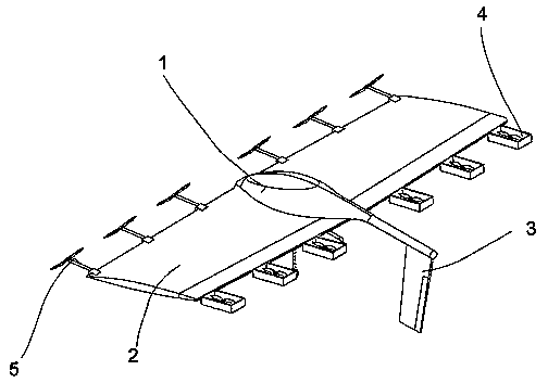
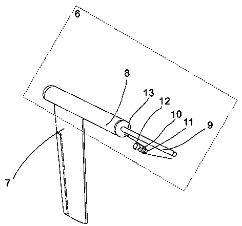
[0040] Embodiment 1 of the present invention discloses a fixed-wing aircraft that can be lifted vertically, including a fuselage 1, wings 2, a retractable empennage 3, a rear rotor mechanism 4 and a front rotor mechanism 5; the wings 2 are symmetrically arranged on the fuselage 1 on both sides; the telescopic empennage 3 is arranged on the tail of the fuselage 1; the rear rotor mechanism 4 is arranged on the rear side of the wing 2, and the rear rotor mechanism 4 includes a retractable telescopic mechanism 15; the front rotor mechanism 5 advances along the The direction is set on the front side of the wing 2, and the front rotor mechanism 5 can be tilted upwards by 0-90°.

[0041] The beneficial effects of the above preferred technical solutions are: a vertical liftable fixed-wing aircraft disclosed by the present invention, wherein the telescopic empennage 3 can be stretched back and forth according to the requirements of use, and the empennage 7 and the aircraft can be increa...

Embodiment 2

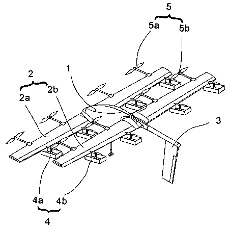
[0059] A fixed-wing aircraft capable of vertical lift, comprising a fuselage 1, wings 2, a retractable empennage 3, a rear rotor mechanism 4 and a front rotor mechanism 5;

[0060] The wing 2 comprises a first group of wings 2a and a second group of wings 2b, the first group of wings 2a and the second group of wings 2b are located on different horizontal planes, and are located on different vertical planes, the first group of wings 2a and the second group of wings 2b The second group of wings 2b are all symmetrically arranged on both sides of the fuselage, the front sides of the first group of wings 2a and the second group of wings 2b are all provided with a front rotor mechanism 4, the first group of wings 2a and the second group of wings The rear side of the wing 2b is provided with a rear rotor mechanism 5;

[0061] The retractable empennage 3 is arranged on the afterbody of the fuselage 1; the rear rotor mechanism 4 is arranged on the rear side of the wing 2, and the rear ...


PUM


Abstract

The invention discloses a vertical take-off and landing fixed-wing aircraft, which comprises a fuselage, a wing, a telescopic tail, a rear rotor structure and a front rotor structure; the fixed-wing aircraft comprises an airframe, a wing, a telescopic tail, a rear rotor structure and a front rotor structure. The wing is symmetrically arranged on both sides of the fuselage. The telescopic tail finis arranged at the tail part of the fuselage. The rear rotor structure is arranged on the rear side of the wing, and the rear rotor structure can be extended and retracted up and down. The forward rotor structure is arranged on the forward side of the wing along the advancing direction, and the forward rotor structure can tilt up to 0- 90DEG. The telescopic tail can be telescoped forward and backward according to the service requirements, so that the stability of flight process can be improved. The rear rotor structure can be expanded and retracted up and down according to the service requirements, so as to reduce the drag during flight; the front rotor structure can tilt from horizontal direction to vertical upward direction, which can provide lift, and can increase forward power and reduce drag. The invention also provides sufficient lifting force through the cooperation of the front rotor structure and the rear rotor structure, so that the ascending, descending and hovering actionscan be completed.

Description

technical field [0001] The invention relates to the technical field of aircraft, and more specifically relates to a fixed-wing aircraft capable of vertical lift. Background technique [0002] Existing aircrafts are generally divided into fixed-wing aircrafts and rotary-wing aircrafts. Among them, the rotorcraft mainly controls the rotation of the propeller structure to generate lift of different sizes so as to achieve the purpose of controlling the vertical take-off and landing of the rotorcraft in the vertical direction; however, there are obvious defects in the flight speed and stability of the rotorcraft. The fixed-wing aircraft has greater flight speed and more stable long-distance flight capability than the rotary-wing aircraft; however, the take-off and landing operations of the fixed-wing aircraft need to be realized through the taxi runway, which takes up a large space for take-off and landing. As a result, the conditions of use of the fixed-wing aircraft are limite...

Claims


Application Information

Patent Timeline
Patent Type & Authority Applications(China)
IPC IPC(8): B64C27/28B64C27/30B64C5/06B64C5/12
CPCB64C27/28B64C5/06B64C5/12B64C27/30
Inventor 李玉龙王志成
Owner FOSHAN SHENFENG AVIATION SCI & TECH
Why Eureka
Try Eureka