Method for building upper semi-circular arch roof lining of industrial furnace pipeline

A technology for lining and industrial furnace, applied in furnace, lining repair, furnace components, etc., can solve problems such as the decline in the quality of the insulation layer masonry, the decline in the plumpness of the block mortar, and the opening of the mortar joints.

Inactive Publication Date: 2019-01-25
CHINA MCC20 GRP CORP
View PDF7 Cites 3 Cited by
  • Summary
  • Abstract
  • Description
  • Claims
  • Application Information

AI Technical Summary

Problems solved by technology

The masonry quality of the working layer in this way is guaranteed, but the masonry quality of the heat insulation layer is significantly reduced, resulting in air leakage from the pipes and redness of the shell, which affects the normal production and operation of the industrial furnace; in order to emphasize the masonry quality of the heat insulation layer, there are also advanced The construction method of building the heat insulation layer and then building the working layer, this construction sequence has caused great difficulties for the building of the working layer, because when building the working layer, there are heat-insulating bricks on the top of the pushed bricks, and there are tires on the bottom. It is difficult to ensure the normal operation of each brick in a limited arc-shaped space. This masonry method seems to follow the quality rule of concealing the heat insulation layer first and then building the working layer. However

Method used


Image

  • Method for building upper semi-circular arch roof lining of industrial furnace pipeline

Examples


Embodiment Construction

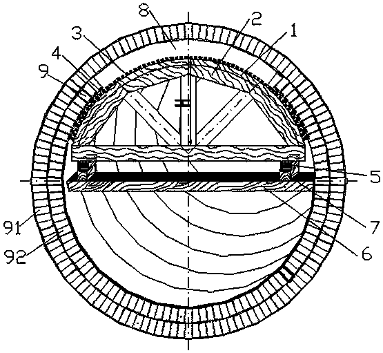
[0017] Example figure 1 As shown, the method for building the semi-circular arch lining on the industrial furnace pipeline of the present invention comprises the following steps:

[0018] Step 1. Manufacturing last tires and accessories. The last tires include the first tire last piece 1, the second tire last piece 2 and the tire last strip 3. The accessories include small wooden wedges 4, large wooden wedges 5, cross-arm wood 6, and raised sleepers 7 ;According to the diameter D of the masonry layer 砌 Subtract the thickness δ of the last tire 3 to calculate the diameter D of the first last tire 1, D=D 砌 -δ, the calculation formula for the diameter d of the second last tire 2 is d=(D- 10~20mm), the arch height H of the first last tire 1 and the second last tire 2 =D 砌 / 2-100~300mm; the length of last tire strip 3 is the brick length plus 20~30mm;

[0019] Step 2: Assembling nails and supporting the tire last, the cross-arm 6 is horizontally arranged under the masonry layer ...


PUM

PropertyMeasurementUnit
Lengthaaaaaaaaaa
Widthaaaaaaaaaa
Thicknessaaaaaaaaaa

Abstract

The invention discloses a method for building an upper semi-circular arch roof lining of an industrial furnace pipeline, which comprises the following steps of: manufacturing a special last tire and asupport of the the special last tire to achieve masonry, wherein the last tire comprises a first last tire piece, a second last tire piece and a last tire strip, the diameter of the first last tire piece is larger than that of the second last tire piece, assembling nails and supporting the last tire, wherein the first last tire piece and the second last tire piece are positioned at the inner sideand outer side in the masonry direction, an end head of the inner side of the last tire strip is overlapped with a front ring brick, and the last tire is fixed after the built brick is inspected; building heat insulating layer bricks and working layer bricks on the supported last tire from inside to outside, building the bricks according to a ring until a closing brick is completely inserted, andfinishing the building of the whole ring; lowering down the last tire and moving out the last tire, checking the masonry effect, after the masonry is qualified, the last tire is erected at the position of a next ring according to the same method, and the next ring of bricks is built until the lining of the semi-circular arch roof of the whole pipeline is completely built. According to the method,the building blocks are visually controllable in the masonry process, the mortar fullness and the final masonry position of the building blocks are ensured, the masonry quality is ensured, and the service life is prolonged.

Description

technical field [0001] The invention relates to a method for building an inner lining of a semi-circular vault on an industrial furnace pipeline. Background technique [0002] For a long time, in order to prolong the service life of industrial furnaces and improve the quality of lining installation, people have explored new ideas in various aspects and achieved good results. The piping system is an important part of the industrial furnace. The piping plays different roles in the industrial furnace and its lining structure is also different. The different lining structures have different installation methods. [0003] Due to the fully enclosed structural characteristics of industrial furnace pipes, clay bricks (high alumina bricks) for the working layer are generally used to build the upper semicircular vault of the pipeline, and then lightweight clay bricks (lightweight bricks) for the heat insulation layer are built. High alumina bricks or mullite insulation bricks, etc.),...

Claims


Application Information

Patent Timeline
IPC IPC(8): F27D1/04F27D1/16
CPCF27D1/045F27D1/16F27D1/1621
Inventor 朱华金敏曹始锋魏尚起魏连霞
Owner CHINA MCC20 GRP CORP
Why Eureka
Try Eureka