
Laser tracking technology-based target plate device and target plate positioning method

A technology of laser tracking and laser tracker, which is applied in the direction of using optical devices, measuring devices, instruments, etc., can solve the problems of display accuracy deviation of safety-critical symbols, failure to meet product performance requirements, and high requirements for site flatness, so as to avoid safety problems. The effects of reducing hidden dangers, shortening operation time, and reducing site requirements

Active Publication Date: 2019-01-25
LUOYANG INST OF ELECTRO OPTICAL EQUIP OF AVIC
View PDF4 Cites 21 Cited by
  • Summary
  • Abstract
  • Description
  • Claims
  • Application Information

AI Technical Summary

Problems solved by technology

At present, the accuracy of the traditional target positioning method is low. Due to the large deviation of measurement accuracy, it cannot meet the product performance requirements. Some safety-critical symbols display large deviations in accuracy that may affect flight safety.
In addition, the traditional target board can only be used to correspond to one aircraft type, and the placement method requires special equipment to level the aircraft, which has high requirements on the flatness of the site, and the measurement process is cumbersome and time-consuming
In China, the development of airborne equipment target device and target positioning method is still in its infancy

Method used


Image

  • Laser tracking technology-based target plate device and target plate positioning method
  • Laser tracking technology-based target plate device and target plate positioning method
  • Laser tracking technology-based target plate device and target plate positioning method

Examples


Embodiment Construction

[0029] Now in conjunction with embodiment, accompanying drawing, the present invention will be further described:

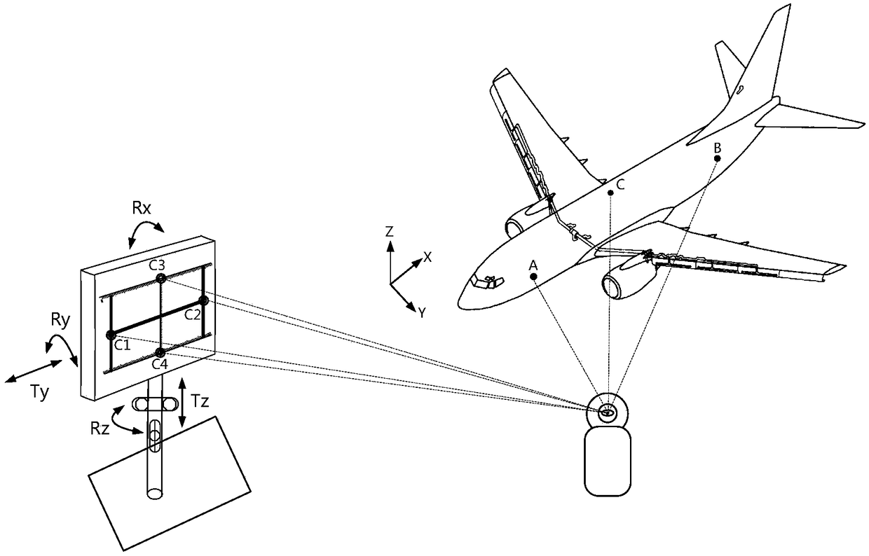
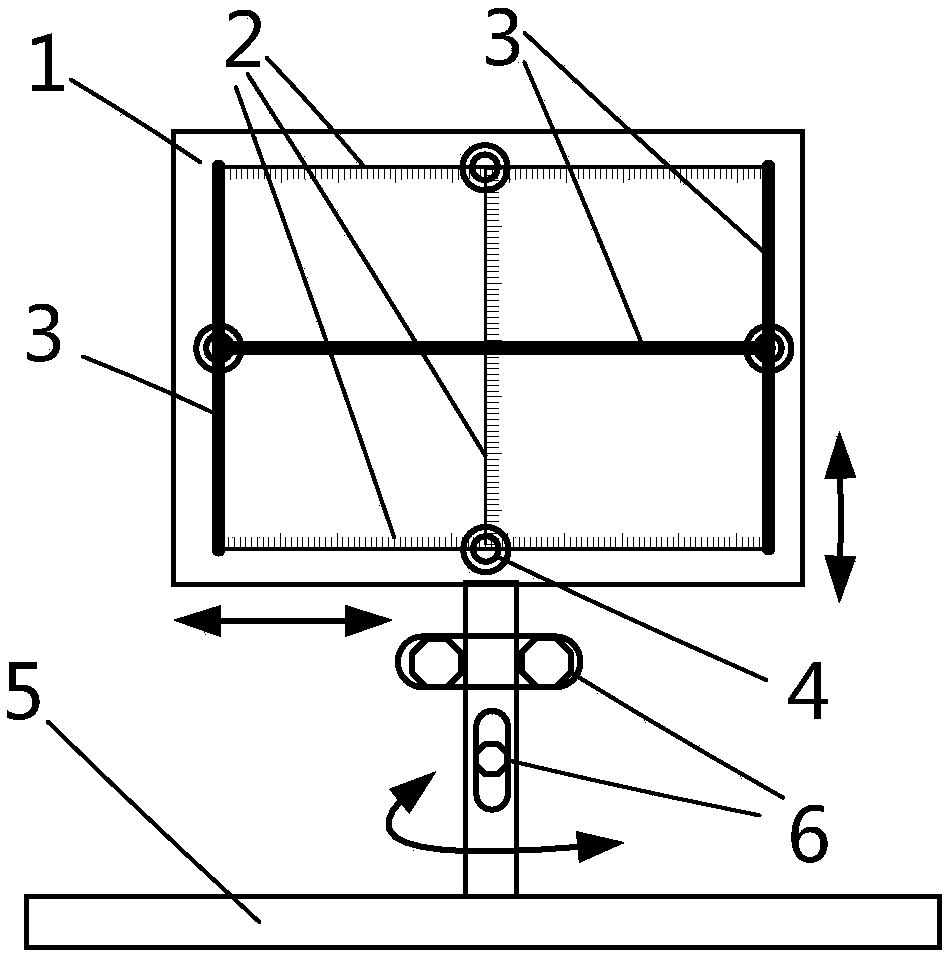
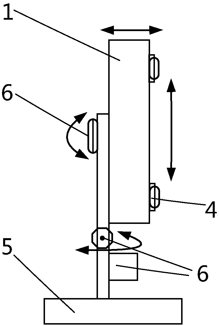
[0030] The invention relates to a target plate device and a target plate positioning method based on laser tracking technology. The target plate device based on laser tracking technology includes a target plate, a laser tracker target, a base, and an adjustment device. There is a reference mark on the target board, which is used to draw the calibration target line; the laser tracker target can receive and reflect the signal of the laser tracker, and is used to install on the target board, and complete the spatial position measurement of the target board in the aircraft body coordinate system The adjustment device can adjust the base bracket to make the target plate complete three axial translation and rotation adjustments; the base is used to place the target plate on the aircraft target calibration platform to keep the target calibration device stable. The targ...


PUM


Abstract

The invention belongs to a laser tracking technology-based target plate device and a target plate positioning method. The laser tracking technology-based target plate device includes a target plate, laser tracker targets, a base, and an adjustment device; the target plate is provided with datum identifiers through which target correction lines can be drawn; the laser tracker targets can receive and reflect laser tracker signals and are mounted on the target plate; the spatial position measurement of the target plate in an aircraft body coordinate system can be completed through the laser tracker targets; the bracket of the base can be adjusted through the adjustment device, so that the three-axial-direction translation and rotation adjustment of the target plate can be completed; and the target plate can be arranged on an aircraft target correction platform through the base, so that a target correction device can be kept stable. According to the target positioning method, the referencepoints of the target plate are spatially located in the aircraft body coordinate system; and spatial positional relations between target lines and the axes of an aircraft are calculated, so that theangle of the target plate in different axial directions can be adjusted, and therefore, the target plate maintains the same posture as the aircraft.

Description

technical field [0001] The invention belongs to an airborne equipment target board device and a target board positioning method, and relates to a target board device and a target board positioning method based on laser tracking technology. Background technique [0002] Airborne equipment target calibration refers to the combination of mechanical adjustment and electrical adjustment, so that the characters displayed on the airborne equipment are aligned with the external scene. When performing target calibration on head-up display (HUD), enhanced vision equipment (EVS), and other airborne equipment, the most critical step is to complete the positioning of the target board. At present, the accuracy of the traditional target plate positioning method is low. Due to the large measurement accuracy deviation, it cannot meet the product performance requirements. Some safety-critical symbols display large accuracy deviations, which may affect flight safety. In addition, the traditio...

Claims


Application Information

Patent Timeline
IPC IPC(8): G01B11/00
CPCG01B11/002
Inventor 王鹏程丁浩李航冯国昌
Owner LUOYANG INST OF ELECTRO OPTICAL EQUIP OF AVIC
Learn More