Ballot sorting module adopting side open paper feeding channel

A paper-feeding channel and channel technology, applied in the field of ballot sorting modules, can solve problems such as error-prone, time-consuming and labor-intensive, and achieve the effects of facilitating maintenance, improving sorting efficiency, and reducing stress.

Inactive Publication Date: 2019-01-25
CHENGDU CAS INFORMATION TECH CO LTD
8 Cites 1 Cited by

AI-Extracted Technical Summary

Problems solved by technology

However, the existing reading machines based on image recognition technology only have scanning and image screening functions, and the screened ballots are still stacked in the pa...

Method used

When there is a card ballot or when the ballot sorting module needs to be maintained, open the locking structure between the paper feeding assembly 2 and the paper pressing assembly 1, and rotate the pressing paper assembly 1 upwards, and the stuck paper can be taken out ballots, or maintain the ballot sorting module. The reader needs a certain reaction time to read the ballots, so the length of the first channel 7 must meet the reaction time of the reader. Usually, to complete the sorting of an A4-sized ballot, the length of the entire ballot sorting module is about 630mm. If the ballots are larger, then a longer ballot sorting module needs to be made. Therefore, if the axis of rotation of the paper pressing assembly 1 relative to the paper feeding assembly 2 is perpendicular to the conveying direction of the ballot paper, the moment acting on the rotating parts between the paper pressing assembly 1 and the paper feeding assembly 2 is relatively large, resulting in damage to the rotating parts The speed is increased. At the same time, when the paper press assembly 1 is opened, in order to ensure sufficient operating space, the paper press assembly 1 is opened at a larger angle, which increases the floor space, and at the same time easily causes the center of gravity of the ballot sorting module to be unstable and topple over. Therefore, in this embodiment, by making the relative rotation axis of the paper pressing assembly 1 and the paper feeding assembly 2 parallel to the conveying direction of the ballot pape...

Abstract

The invention belongs to the technical field of ballot counters, and discloses a ballot sorting module adopting a side open paper feeding channel. The ballot sorting module comprises a first channel,wherein a positioning connection structure is arranged between the first channel and a reader, so that an inlet of the first channel is in direct communication with an outlet of the reader; a second channel and a third channel are respectively arranged at one end, far away from the reader, of the first channel; a rotary sorting element is arranged between inlets of the second channel and the thirdchannel, and is connected with a first driving device for driving the sorting element to rotate; when the sorting element is positioned at a starting position, the second channel is communicated withthe first channel to form a first sorting channel, and when the sorting element is positioned at a final position, the third channel is communicated with the first channel to form a second sorting channel. The ballot sorting module can complete the automatic sorting of ballots, avoid human errors, and improve the sorting efficiency.

Application Domain

Technology Topic

Point of entryHuman error +3

Image

  • Ballot sorting module adopting side open paper feeding channel
  • Ballot sorting module adopting side open paper feeding channel
  • Ballot sorting module adopting side open paper feeding channel

Examples

  • Experimental program(4)

Example Embodiment

[0034] Example 1:
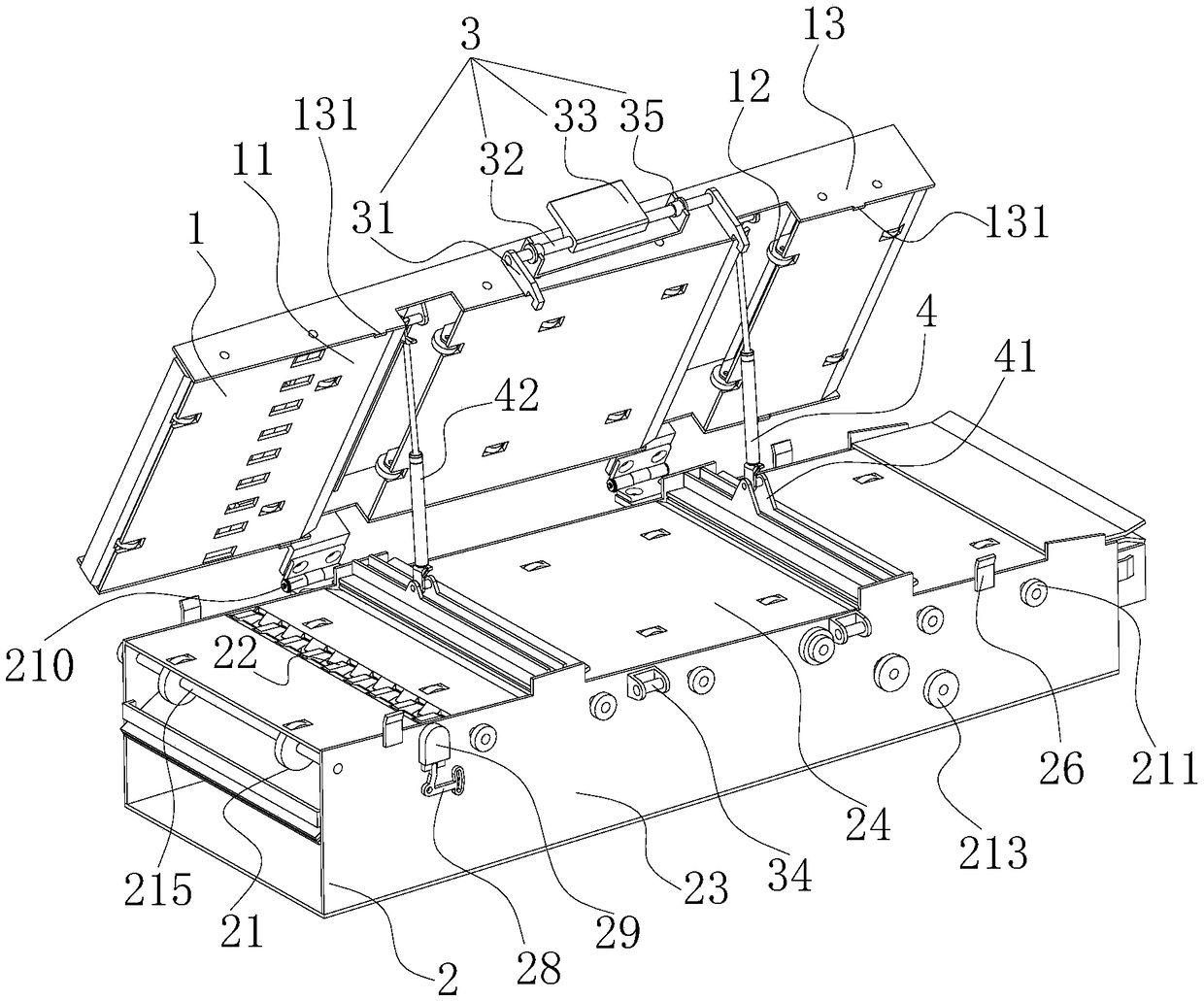
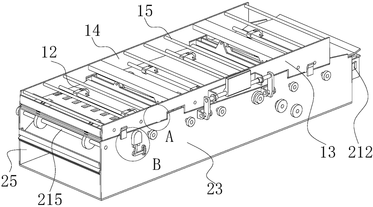
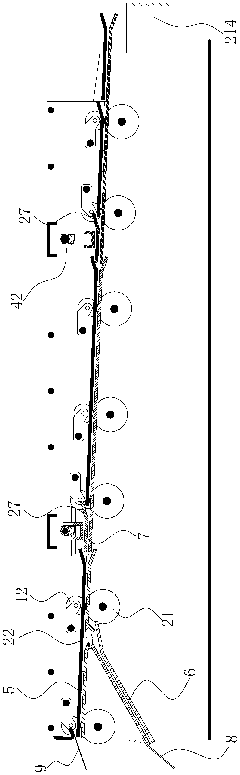
[0035] This embodiment provides a ballot sorting module using a side-opening paper-feeding channel, which includes a first channel 7; a positioning connection structure is provided between the first channel 7 and the reader so that the first channel 7 The entrance is directly connected with the exit of the reader; the second channel 5 and the third channel 6 are respectively provided at the end of the first channel 7 away from the reader; between the entrance of the second channel 5 and the entrance of the third channel 6 A rotating sorting element 22 is arranged in the middle; the sorting element 22 is connected with a first driving device that drives it to rotate, and when the sorting element 22 is at the starting position, the second channel 5 is in communication with the first channel 7 , Forming a first sorting channel, when the sorting element 22 is at the end position, the third channel 6 is connected to the first channel 7 to form a second sorting channel;
[0036] The first sorting channel includes a paper pressing assembly 1 and a paper feeding assembly 2; one side of the paper pressing assembly 1 is rotatably connected with one side of the paper feeding assembly 2, and the paper pressing assembly 1 and the paper feeding assembly 2 rotate relatively The axis of rotation of is parallel to the conveying direction of the ballot; a locking structure is provided between the other side of the paper pressing assembly 1 and the other side of the paper feeding assembly 2 to lock the paper pressing assembly 1 and the paper feeding assembly 2, The first sorting channel is formed.
[0037] Such as figure 1 , 3 As shown in and 4, the paper feeding assembly 2 includes a first lower side plate 23 and a second lower side plate 25 that are arranged oppositely; the first lower side plate 23 and the second lower side plate 25 are respectively fixedly connected There is a first bottom plate 24 and a plurality of rotating shafts 215; the plurality of rotating shafts 215 are all arranged below the first bottom plate 24, and the plurality of rotating shafts 215 are arranged side by side along the conveying direction of the ballot, and each rotating shaft 215 is fixed There is a paper feed roller 21 coaxial with it, and a plurality of said rotating shafts 215 are connected in transmission. In this example, a plurality of rotating shafts 215 are connected by a timing belt, and the plurality of rotating shafts 215 rotate in the same direction at a constant speed. Any one of the rotating shafts 215 is connected to a second driving device that drives it to rotate; in this embodiment, the second driving device includes a servo motor and an active synchronous belt wheel 213 fixed at the output end of the servo motor, and a synchronous belt wheel 213 It is connected to the driven synchronous pulley 211 on any one of the rotating shafts 215 through a synchronous belt (not shown in the figure). The first bottom plate 24 is provided with an escape hole for avoiding the paper feed roller 21.
[0038] Such as figure 1 , 3 As shown in and 4, the paper pressing assembly 1 is arranged above the paper feeding assembly 2, and the paper pressing assembly 1 and the paper feeding assembly 2 are connected in rotation through a hinge 210. The paper pressing assembly 1 in this embodiment includes a first upper side plate 13 and a second upper side plate 14 arranged oppositely; a first upper side plate 13 and a second upper side plate 14 are fixedly connected between the first upper side plate 13 and the second upper side plate 14. The top plate 11; above the first top plate 11 is provided with a plurality of paper pressing rollers 12, the paper pressing roller 12 and the paper feeding roller 21 are arranged in one-to-one correspondence; specifically, the first upper plate 13 and the second upper plate 14 A fixed shaft 16 is fixedly connected therebetween. The pressure paper roller 12 is swinging around the central axis of the fixed shaft 16. A torsion spring (not shown in the figure) is provided between the fixed shaft 16 and the pressure paper roller 12 to make the paper pressure The roller 12 is pressed tightly on the paper feed roller 21, thereby compressing the ballot paper, and completing the conveying of the ballot paper. It is also possible to provide a tension spring between the paper pressing roller 12 and the first top plate 11 to make the paper pressing roller 12 tightly press on the paper feed roller 21. It can be understood that, in practice, the pressing roller 12 can be pressed against the paper feed roller 21 by other existing methods. An escape hole for avoiding the platen roller 12 is opened on the first top plate 11. Such as image 3 with 4 As shown, the gap between the first top plate 11 and the first bottom plate 24 is the first sorting channel. To ensure the gap between the first top plate 11 and the first bottom plate 24, such as figure 1 , 2 As shown in and 5, in this embodiment, a limiting protrusion 131 extending toward the paper feeding assembly 2 is fixed on the first upper side plate 13. It can be understood that, in practice, the limiting protrusion 131 extending toward the paper pressing assembly 1 may also be fixed on the first lower side plate 23. To improve the structural strength of the paper pressing assembly 1, such as figure 2 As shown, a plurality of reinforcing rods 15 are fixed between the first upper side plate 13 and the second upper side plate 14. In the embodiment, such as Figure 4 As shown, the third channel 6 is provided below the first sorting channel, and includes a second top plate 61 and a second bottom plate 62 that are arranged oppositely; both sides of the second top plate 61 are connected to the first lower side plate 23 and the second bottom plate respectively. The side plate 25 is fixedly connected, and the two sides of the second bottom plate 62 are respectively fixedly connected to the first lower side plate 23 and the second lower side plate 25. The gap between the second top plate 61 and the second bottom plate 62 is the third channel 6. The gap is opened on the first bottom plate 24. A gap is opened on the side of the first sorting channel facing the third channel 6, such as Figure 4 As shown, in this embodiment, the gap is opened on the first bottom plate 24, and the sorting element 22 is arranged in the gap. The first driving device makes the sorting element 22 at the origin position or the end position, thereby completing the ballot Automatic sorting. It can be understood that the third channel 6 may also be arranged above the first sorting channel, and at this time, the notch is opened on the first top plate 11. The sorting element 22 can be made into a whole board, but in order to increase the reaction speed of the sorting element 22, the weight of the sorting element 22 should be minimized, so as figure 1 As shown, in this embodiment, the sorting element 22 is made as a small block. In order to prevent card votes, there are multiple sorting elements 22, and the multiple sorting elements are evenly arranged in a direction parallel to the rotating shaft 215. Both the first top plate 11 and the first bottom plate 24 are provided with escape holes for avoiding the sorting element 22.
[0039] Such as figure 1 with 2 As shown, the positioning connection structure between the first channel 7 and the reader includes a positioning protrusion 212 and a positioning groove (not shown in the figure) matching the positioning protrusion 212. It can be understood that one of the first channel 7 and the reader is fixedly connected to the positioning protrusion 212, and the other is provided with the positioning groove. In this embodiment, the positioning protrusions 212 shown are fixed on both the first lower side plate 23 and the second lower side plate 25, and positioning grooves adapted to the positioning protrusions 212 are respectively provided on the reader. To detect whether the exit of the reader is aligned with the entrance of the first channel 7, in this embodiment, a sensor 214 is provided between the first channel 7 and the reader.
[0040] The locking structure can be realized by using existing technology, such as figure 1 with 2 As shown, the locking structure 3 in this embodiment includes a latching hook 31 and a latching post 34 that cooperate with each other; one end of the latching hook 31 is rotatably arranged on the paper pressing assembly 1, and the latching post 34 is fixed on the The paper feed assembly 2 is mentioned. Such as figure 1 As shown, a support 35 is fixed on the first upper side plate 13, a rotating shaft 32 is provided on the support 35, and both ends of the rotating shaft 32 are fixed with the hooks 31, and the hooks 31 face One side of the first upper side plate 13 is provided with a groove adapted to the clamping column 34. The clamping post 34 is cylindrical, the clamping post 34 is fixed on the first lower side plate 23, and the groove of the hook 31 is clamped on the clamping post 34, that is, the paper pressing assembly 1 and the paper feeding assembly 2 are locked. For easy operation, such as figure 1 As shown, a handle 33 is fixed on the rotating shaft 32. To further facilitate operation, a first spring (not shown in the figure) is provided between the hook 31 and the paper pressing assembly 1, and the lower side wall of the groove of the hook 31 is chamfered to make the The hook 31 is clamped with the locking column 34 under the action of the first spring.
[0041] The first driving device can be implemented using existing technologies such as motors. Such as figure 1 with 2 As shown, the first driving device in this embodiment is a rotating electromagnet 29. The rotating electromagnet 29 is fixed on the first lower side plate 23. In this embodiment, the rotating electromagnet 29 is realized by a rotating electromagnet of model KSA30H11A. To facilitate the debugging of this ballot sorting module, such as figure 1 with 2 As shown, the rotating electromagnet 29 is connected with an angle adjustment device that adjusts its installation angle to change the start position and end position of the sorting element 22, so that when the sorting element 22 is at the start position, the first channel 7 and The second channel 5 is directly connected to each other; when the sorting element 22 is at the end position, the first channel 7 and the third channel 6 are directly connected to each other. Specifically, in this embodiment, as figure 1 with 2 As shown, the rotating electromagnet 29 is rotationally connected with the first lower side plate 23, and the rotation axis of the rotating electromagnet 29 coincides with the rotation axis of the sorting element 22. Such as Image 6 As shown, the angle adjusting device includes an adjusting rod 28; the middle of the adjusting rod 28 is rotatably connected to the first lower side plate 23, one end of the adjusting rod 28 is inserted into the slot of the rotating electromagnet 29, and the other of the adjusting rod 28 An arc-shaped elongated hole 281 is opened at one end, a screw (not shown in the figure) is arranged in the elongated hole 281, and a threaded hole for threaded engagement with the screw is opened on the corresponding first lower side plate 23. Therefore, by changing the position of the adjusting rod 28, the installation position of the rotary electromagnet 29 can be changed.
[0042] working principle:
[0043] According to the information of the ballot, such as gender information or valid and invalid information, the reader judges which sorting channel the ballot should pass through to the corresponding receiving tray, and sends the signal to the first driving device, which is based on the information sent by the reader The signal drives the sorting element 22 to rotate to the origin position or the end position. At the same time, the ballot enters the first channel 7 through the exit of the reader, and the pressure roller 12 and the paper feed roller 21 clamp the ballot, driven by the second driving device , The paper feed roller 21 rotates to transport the ballots away from the reader. If the sorting element 22 is located at the origin, that is image 3 In the position shown, the ballot will be sent out from the second channel 5 and enter the paper receiving tray corresponding to the second channel 5 (not shown in the figure); if the sorting element 22 is at the end position, that is Figure 4 In the position shown, the ballot will be sent out from the third channel 6 into the paper receiving tray corresponding to the third channel 6 (not shown in the figure). Thereby, the automatic sorting of ballots is completed, human error is avoided, and the sorting efficiency is greatly improved.
[0044] When a card ballot appears or the ballot sorting module needs to be maintained, open the locking structure between the paper feeding assembly 2 and the paper pressing assembly 1, and rotate the paper pressing assembly 1 upward to take out the stuck ballot, or Maintain this ballot sorting module. The reader needs a certain reaction time to read the ballot, so the length of the first channel 7 must meet the reaction time of the reader. Usually, to sort an A4 paper ballot, the length of the entire ballot sorting module is about 630mm. If the ballot is larger, then a longer ballot sorting module needs to be made. Therefore, if the axis of rotation of the paper pressing assembly 1 relative to the paper feeding assembly 2 is perpendicular to the conveying direction of the ballots, the torque acting on the rotating parts between the paper pressing assembly 1 and the paper feeding assembly 2 will be larger, resulting in damage to the rotating parts The speed is increased, and at the same time, in order to ensure sufficient operating space when the paper pressing assembly 1 is opened, the opening angle of the paper pressing assembly 1 is larger, which increases the floor area, and at the same time easily causes the center of gravity of the ballot sorting module to be unstable and toppling. Therefore, in this embodiment, by making the relative rotation axis of the paper pressing assembly 1 and the paper feeding assembly 2 parallel to the conveying direction of the ballot, the torque acting on the rotating member between the paper pressing assembly 1 and the paper feeding assembly 2 is reduced, At the same time, it provides a larger opening and closing angle in a limited space for easy operation. What needs to be said is that the reader adopts existing technology. In this embodiment, the reading machine is realized by the intelligent ticket counting integrated machine disclosed by the applicant in the patent CN201710178946.0. It is understandable that you only need to take out the paper output bin of the smart ticket counting machine in CN201710178946.0, and then connect the entrance of the first channel of the scanning ballot sorting module to the exit of the smart ticket counting machine.

Example Embodiment

[0045] Example 2:
[0046] After opening the paper pressing assembly 1, if there is no supporting structure, it is necessary to manually hold the paper pressing assembly 1 to operate, which is inconvenient and unsafe. For this reason, this embodiment is based on the first embodiment. A supporting structure 4 is provided between the paper assembly 1 and the paper feeding assembly 2. When the paper pressing assembly 1 and the paper feeding assembly 2 are opened, the supporting structure keeps the paper pressing assembly 1 and the paper feeding assembly 2 in an open state. Specifically, such as figure 1 As shown, the supporting structure 4 includes a gas spring 42; both ends of the gas spring 42 are hinged to the paper pressing assembly 1 and the paper feeding assembly 2 respectively. Such as image 3 with 4 As shown, a first mounting seat 41 is fixedly connected between the first lower side plate 23 and the second lower side plate 25. The first mounting seat 41 is located above the first bottom plate 24. The cylinder of the gas spring 42 and the first The mounting seat 41 is hinged, and the piston rod of the gas spring 42 is hinged to a second mounting seat fixedly connected between the first upper side plate 13 and the second upper side plate 14. The first top plate 11 is provided with an escape notch for avoiding the gas spring 42 and the first mounting seat 41. In this embodiment, in order to prevent ballots from being stuck, a third top plate 27 is fixed between the first mounting seat 41 and the first bottom plate 24. When the paper feeding assembly 2 and the paper pressing assembly 1 are locked, the third top plate 27 and the first A top plate 11 is coplanar. Since the first top plate 11 is disconnected at the support structure 4, in order to avoid the upturning of the ballot, the card ballot will appear, such as Figure 4 As shown, one end of the third top plate 27 facing the reader is provided with a guide portion gradually inclined upward, and the paper feed roller 21 and the paper pressure roller 12 are provided at the position of the guide portion.

Example Embodiment

[0047] Example 3:
[0048] In this embodiment, on the basis of Embodiment 1 or 2, the first sorting channel is gradually inclined upward along the conveying direction of the ballots. In order to slow down the conveying speed of the ballots, to prevent the ballots from quickly rushing out of the ballot sorting channel, causing the ballots to fly off the receiving tray. At the same time, in this embodiment, a first buffer sheet 9 is fixed at the end of the second channel 5 away from the first channel 7; a second buffer sheet 8 is fixed at the end of the third channel 6 away from the first channel 7 . In order to further avoid the problem that the ballots are sent out of the ballot sorting module when the transport speed is too fast, which causes the ballots to rush out of the receiving tray.

PUM

PropertyMeasurementUnit
Length630.0mm
tensileMPa
Particle sizePa
strength10

Description & Claims & Application Information

We can also present the details of the Description, Claims and Application information to help users get a comprehensive understanding of the technical details of the patent, such as background art, summary of invention, brief description of drawings, description of embodiments, and other original content. On the other hand, users can also determine the specific scope of protection of the technology through the list of claims; as well as understand the changes in the life cycle of the technology with the presentation of the patent timeline. Login to view more.

Similar technology patents

Classification and recommendation of technical efficacy words

  • Avoid human error
  • Improve sorting efficiency

Extensible inspection production equipment for smart cards

InactiveCN101049595AImprove sorting efficiencyGood sorting qualitySortingProduction lineHigh volume manufacturing
Owner:GUANGZHOU SANTUO IDENTIFICATION TECH CO LTD
Why Eureka
Try Eureka