Controlling method for lower limb external skeleton robot

A technology of exoskeleton robot and control method, which can be applied in the direction of equipment to help people walk, physical therapy, etc., and can solve the problems of low energy utilization efficiency and heavy mechanism weight

Active Publication Date: 2019-01-29
HEBEI UNIV OF TECH
View PDF7 Cites 8 Cited by
  • Summary
  • Abstract
  • Description
  • Claims
  • Application Information

AI Technical Summary

Problems solved by technology

[0005] The purpose of the present invention is to provide a control method for a wearable lower limb exoskeleton robot in order to solve the problems

Method used


Image

  • Controlling method for lower limb external skeleton robot
  • Controlling method for lower limb external skeleton robot
  • Controlling method for lower limb external skeleton robot

Examples


Embodiment 1

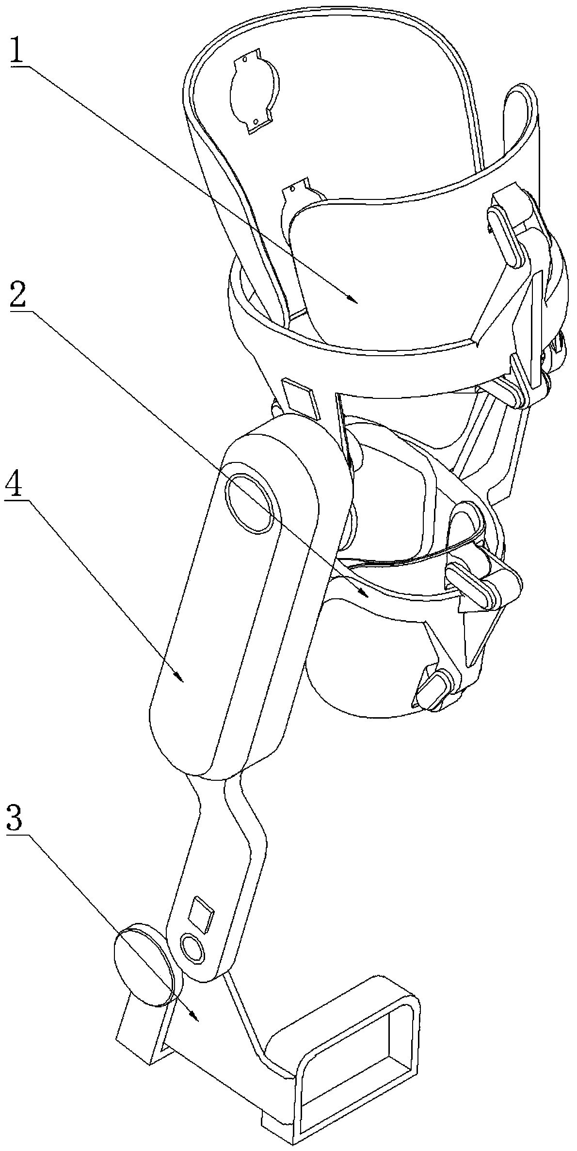
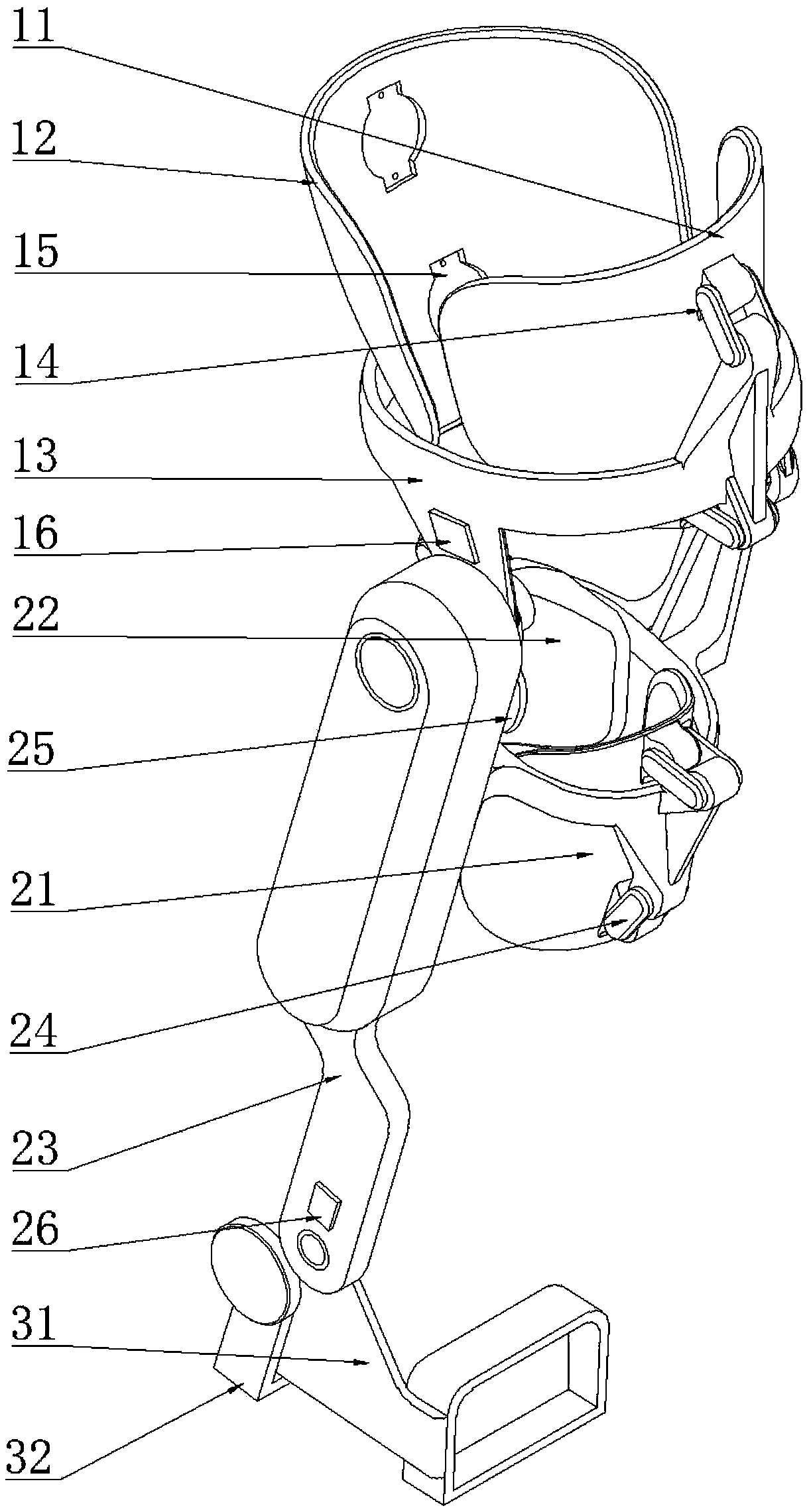
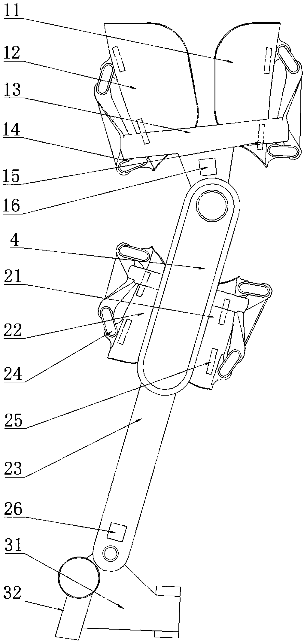
[0118] like Figure 1-Figure 3 As shown, the skeletal robot of this embodiment includes a thigh support part 1, a shin support part 2, a foot support part 3 and a power chamber 4;

[0119] The thigh support part 1 and the shin support part 2 are connected by a set of joints, hereinafter referred to as "exoskeleton knee joint"; the tibia support part 2 and the foot support part 3 are connected by a set of joints, hereinafter referred to as "exoskeleton knee joint" Exoskeleton ankle joint "; the power chamber 4 is fixed on the side of the shin support part 2.

[0120] The thigh support part 1 includes a thigh front support plate 11, a thigh rear support plate 12, a thigh frame 13, a thigh gyroscope and an acceleration sensor 16, and four connecting rods 14 of the thigh. Sensor 15 four.

[0121] The main body of the stock frame 13 is ring-shaped, and the stock front side support plate 11 and the stock rear side support plate 12 are located on the front and rear sides of the rin...

Embodiment 2

[0135] The embodiment of the present invention provides a control method for the exoskeleton robot described in Embodiment 1. The control method includes a motion intention predictor, an energy collection estimator, an energy recovery trigger, a finite-time convergent disturbance observer and a non-singular terminal sliding mode controller, and the specific steps are as follows.

[0136] In the first step, the embedded single-chip microcomputer uses the thigh pressure sensor 15 to collect the contact force F between the thigh and the front support plate 11 and the rear support plate 12 respectively. g1 , F g2 , F g3 , F g4 Utilize the shank pressure sensor 25 to collect the contact force F between the shank and the front side support plate 21 of the tibia and the rear side support plate 22 of the tibia respectively j1 , F j2 , F j3 , F j4 ; Then, according to the following formulas (1)-(4), the expected angle signal q of the knee joint that reflects the trajectory of the...


PUM


Abstract

The invention relates to a controlling method for a lower limb external skeleton robot. The method comprises the steps that a motor and an energy collection device dual-driving system are used as a combination of disturbance and a main control driver, uncertainty disturbance and model uncertainty disturbance which are caused by assistance provided by an energy recycle device form total centralizeddisturbance of the system, a finite time convergence disturbance observer is used for estimating the total centralized disturbance existing in the system, the total centralized disturbance is used ascompensation for a nonsingular terminal slide mold controller, the control moment of the motor is acquired, and control over a motor driving system is completed. According to the controlling method,a limit learning machine is used for online calculating the energy collected by the energy collection device through the pressure of soles and angles and angular velocity of joints, the release time of the energy collection device is calculated by using the estimated energy and the gesture of the external skeleton, control over the energy collection device is completed, and output of the peak moment of the motor is supplemented.

Description

technical field [0001] The invention relates to the technical field of auxiliary robots, in particular to a control method for a wearable walking aid lower extremity exoskeleton. Background technique [0002] In the 21st century, China's aging population is gradually increasing. It is predicted that by 2050, China's elderly population will reach one-third of the total population. Inflammation of the knee joint is the most important condition in the joint diseases of the elderly. According to statistics, 10% of men and 13% of women over the age of 60 suffer from symptoms of arthritis. The knee joint pain caused by arthritis seriously affects the patient's walking ability, which brings many difficulties to the free travel of the elderly. Lower limb exoskeletons are a promising solution for sharing the weight on the knee joints and assisting walking. [0003] Lower extremity exoskeletons are generally divided into powered and unpowered forms. It cooperates with the wearer, se...

Claims


Application Information

Patent Timeline
IPC IPC(8): A61H3/00
CPCA61H3/00A61H2003/007A61H2201/1207A61H2201/1642A61H2201/165A61H2201/5071A61H2201/5084A61H2205/102
Inventor 陈玲玲宋晓伟马申宇王婕
Owner HEBEI UNIV OF TECH
Why Eureka
Try Eureka