Glue dispensing device for filter production processing

A dispensing device and filter technology, applied in the direction of spraying device, device for coating liquid on the surface, mixer with rotating stirring device, etc., can solve problems such as curing, affecting dispensing effect, and rapid temperature drop, and achieve The surface is clean, convenient for subsequent cleaning, and the effect of avoiding accumulation

Inactive Publication Date: 2019-01-29
安徽威成精密制造有限公司
View PDF8 Cites 5 Cited by
  • Summary
  • Abstract
  • Description
  • Claims
  • Application Information

AI Technical Summary

Problems solved by technology

[0004] The object of the present invention is to provide a dispensing device for filter production and processing to solve the problem that the temperature of the glue solution in the circulation process is easy to drop rapidly and solidify, thereby affecting the dispensing effect.

Method used


Image

  • Glue dispensing device for filter production processing
  • Glue dispensing device for filter production processing
  • Glue dispensing device for filter production processing

Examples


Embodiment 1

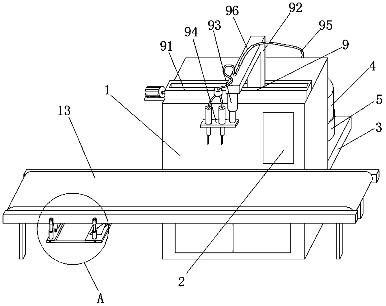
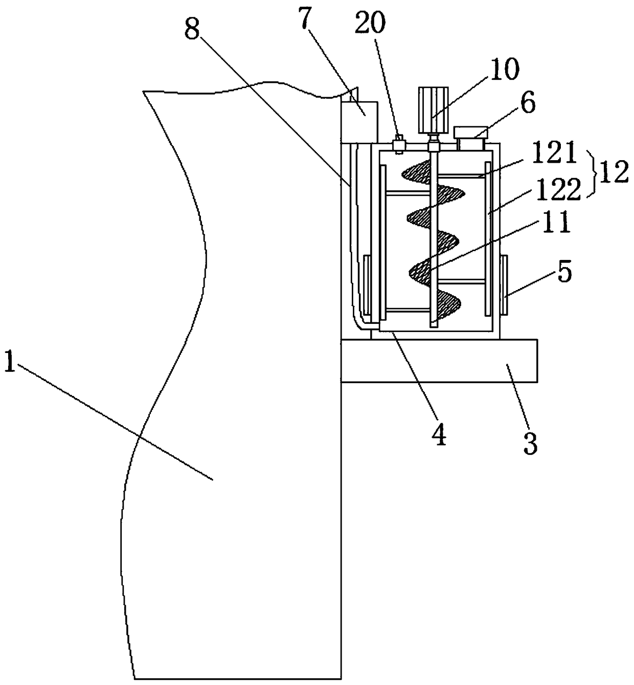
[0024] See Figure 1-4 This embodiment provides a glue dispensing device for filter production and processing, including a frame 1, a control panel 2 is provided on the front of the frame 1, and a support plate 3 is fixedly connected to one side of the frame 1, and the support plate 3 The top of the glue tank 4 is fixedly installed, the surface of the glue tank 4 is sleeved with a heating belt 5, the top of the glue tank 4 is connected with a glue injection pipe 6, and one side of the glue tank 4 is connected with a glue pump 7, preferably a glue pump 7. The model is QBK-40LF46. The top of the frame 1 is equipped with a glue assembly 9 which is connected to the glue pump 7. The top of the glue tank 4 is fixedly installed with a first motor 10, and the output shaft of the first motor 10 is fixedly connected There are mixing blades 11, which are located inside the glue tank 4. Both sides of the mixing blades 11 are fixedly connected with scraper components 12, and the other side ...

Embodiment 2

[0027] See Figure 1-4 , A further improvement is made on the basis of embodiment 1: the lower end of one side of the glue tank 4 is connected with a rubber outlet pipe 8, the glue pump 7 is connected with the glue tank 4 through the rubber outlet pipe 8, and the rubber outlet pipe 8 plays the role of connecting the glue pump 7. , And the glue outlet tube 8 is located at the lower end of one side, which facilitates the outflow of glue, makes the use of glue more thorough, and reduces the residual amount of glue inside the glue tank 4.

[0028] Among them, the dispensing assembly 9 includes a sliding device 91, the top of the sliding device 91 is fixedly connected with an L-shaped bracket 92, and a hydraulic rod 93 is arranged under the L-shaped bracket 92. The preferred model of the hydraulic rod 93 is SFY-001, The bottom of the hydraulic rod 93 is fixedly connected with a glue head 94. The top of the glue head 94 is connected with a pipe 95, which communicates with the glue pump...

Embodiment 3

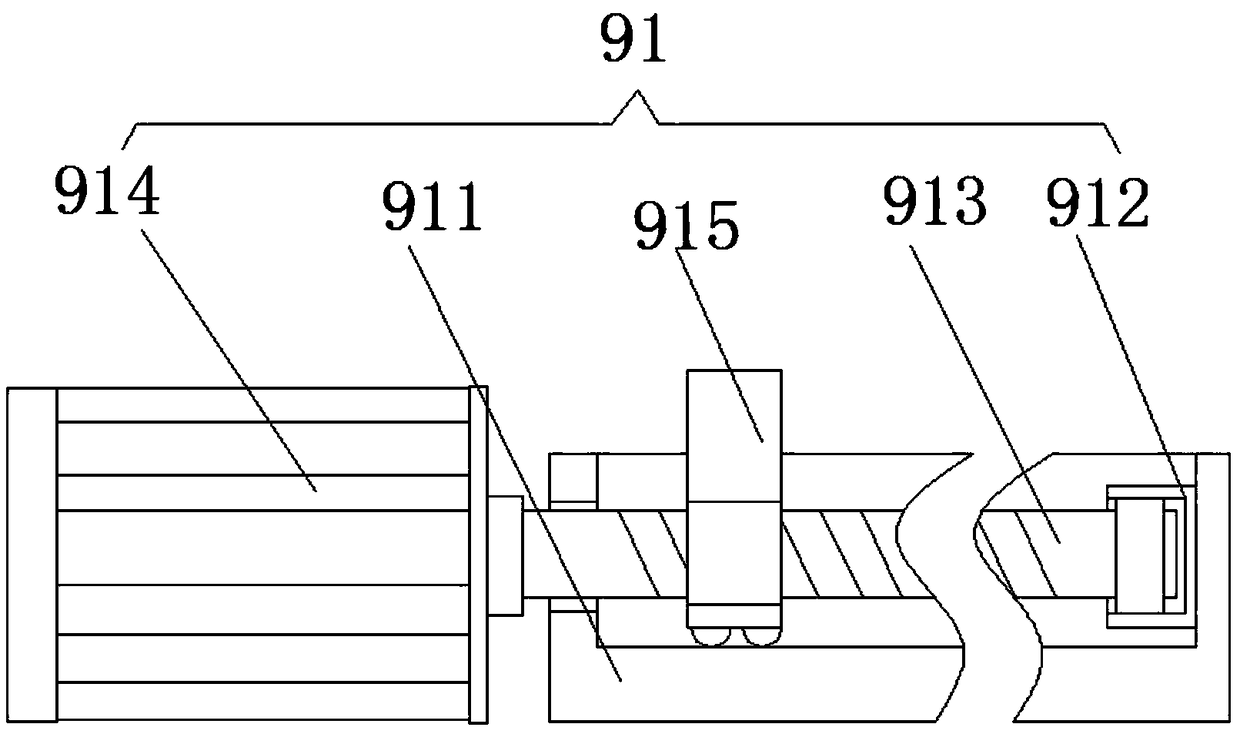
[0030] See Figure 1-4 , On the basis of embodiment 1, a further improvement is made: the sliding device 91 includes a sliding rail 911, the inner wall of the sliding rail 911 is fixedly connected with a rotating seat 912, the inner wall of the rotating seat 912 is rotatably connected with a screw rod 913, the rotating seat 912 A bearing is arranged inside, and the bearing is fixedly connected to the screw rod 913. A second motor 914 is fixedly installed on one side of the sliding rail 911. One end of the screw rod 913 penetrates the sliding rail 911 and is fixedly connected to the output shaft of the second motor 914. The screw rod The surface of the 913 is threadedly connected with a movable sleeve 915, and the movable sleeve 915 is fixedly connected with the L-shaped bracket 92. When the dispensing head 94 needs to move in a horizontal direction, the second motor 914 drives the screw rod 913 to rotate to make the movable sleeve 915 move. In this way, the L-shaped bracket 92 ...


PUM


Abstract

The invention discloses a glue dispensing device for filter production processing. The glue dispensing device comprises a machine frame, wherein a control panel is arranged on the front surface of themachine frame, a supporting plate is fixedly connected to one side of the machine frame, a glue box is fixedly arranged at the top of the supporting plate, a heating tape sleeves the surface of the glue box, a glue injection pipe communicates with the top of the glue box, one side of the glue box communicates with a glue pump, the top of the machine frame is provided with a glue dispensing assembly, the glue dispensing assembly communicates with the glue pump, a first motor is fixedly arranged at the top of the glue box, the output shaft of the first motor is fixedly connected with a stirringblade, the stirring blade is located in the glue box, scraping assemblies are fixedly connected to the two sides of the stirring blade, and the other side of the machine frame is fixedly provided with a conveying belt. According to the glue dispersing device, the problem that glue solution is easy to solidify due to rapid reduction of the temperature in the circulation process is solved, and theglue dispensing effect is influenced.

Description

Technical field [0001] The invention relates to the technical field of filter production, in particular to a glue dispensing device for filter production and processing. Background technique [0002] The power filter is a filter circuit composed of capacitors, inductances, and resistors. The filter can effectively filter out the frequency point of a specific frequency in the power line or the frequency other than that frequency point to obtain a power signal of a specific frequency, or eliminate one The power signal after a specific frequency. At present, network filters have been widely used in communication networks. General network circuit devices are equipped with network filters, such as television network interfaces and notebook network interfaces. Dispensing in the process is a very critical process. Traditional filter dispensing is manually operated by workers. With the development of automation technology, manual dispensing is far from meeting the needs of the industry, ...

Claims


Application Information

Patent Timeline
Patent Type & Authority Applications(China)
IPC IPC(8): B05C5/02B05C11/10B05B15/50B01F15/00B01F7/24
CPCB05B15/50B05C5/027B05C11/1002B05C11/1042B01F27/92B01F35/123
Inventor 吴庆玲
Owner 安徽威成精密制造有限公司
Why Eureka
Try Eureka