Rotary printing electrolytic machining liquid sealing device and method

A non-processing area, flushing technology, applied in electric processing equipment, electrochemical processing equipment, accessories, etc., can solve the problems of divergent flow field, poor flow field distribution, and small flow rate of electrolyte, and achieve increased flow rate, Improve the effect of flow field distribution

Active Publication Date: 2019-01-29
NANJING UNIV OF AERONAUTICS & ASTRONAUTICS
View PDF7 Cites 10 Cited by
  • Summary
  • Abstract
  • Description
  • Claims
  • Application Information

AI Technical Summary

Problems solved by technology

Under this condition, the flow field diverges, and the electrolyte mainly flows through the gap between the workpiece and the upper and lower end surfaces of the fixture and the non-processing areas on the left and right sides. The flow rate of the electrolyte in the processing area is small, and the flow field distribution is poor, resulting in stable processing. Poor performance, prone to short circuit
Especially in the processing of high bosses, the corrosion amount of the workpiece is large, the flow channel in the non-processing area is much larger than the processing gap, and the flow field distribution in the processing area is seriously uneven, resulting in a small local electrolyte flow rate, or even lack of liquid, and the processed products cannot be eliminated in time. gap, resulting in a short circuit between the anode of the workpiece and the cathode of the tool, affecting the processing

Method used


Image

  • Rotary printing electrolytic machining liquid sealing device and method
  • Rotary printing electrolytic machining liquid sealing device and method
  • Rotary printing electrolytic machining liquid sealing device and method

Examples


Embodiment Construction

[0026] Implementation of the present invention - "Spin Printing Electrolytic Machining Liquid Sealing Device and Method"

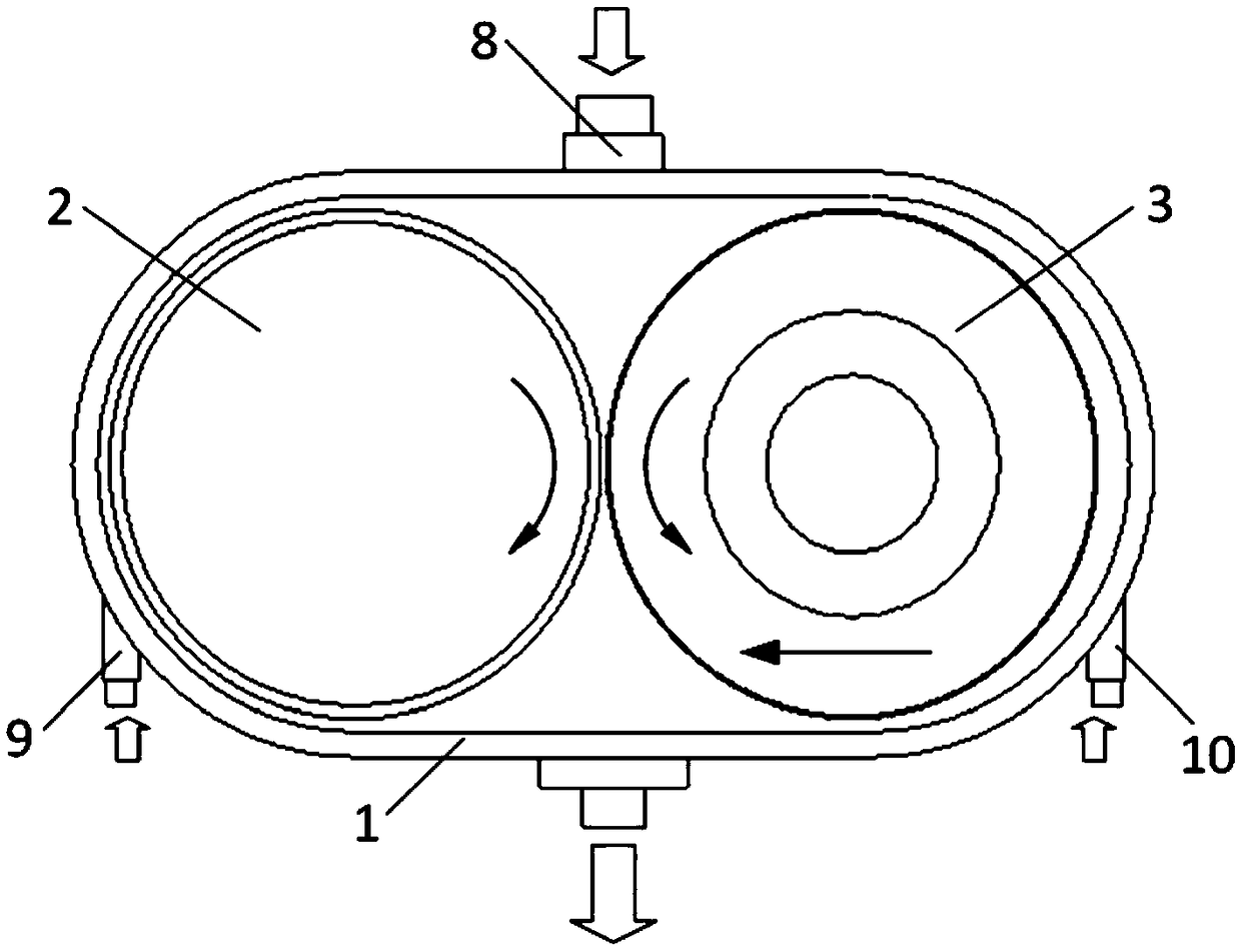
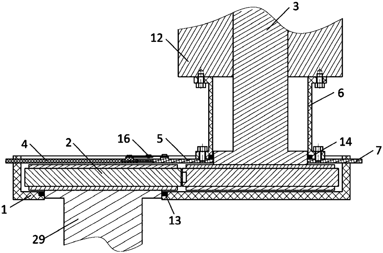
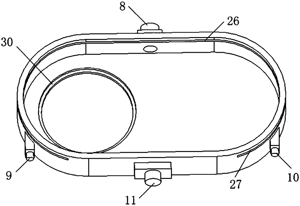
[0027] Such as figure 1 , 2 As shown, the device includes a flushing fixture seat, an auxiliary sealing sleeve, a fixed cover, a retractable cover, a follower cover, a tool cathode unit, a workpiece unit, and a workpiece rotating spindle.

[0028] Such as image 3 As shown, the flushing fixture seat has a main flushing port, a left auxiliary flushing port, a right auxiliary flushing port and a liquid outlet. The main flushing port faces the processing area and flushes from back to front; the left auxiliary flushing port The flushing port and the right auxiliary flushing port are respectively facing the center of the left and right non-processing areas, flushing from front to back, and the flushing pressure of the auxiliary flushing port is not less than the flushing pressure of the main flushing port. The left and right side walls of the flushing fixtur...


PUM


Abstract

The invention relates to a rotary printing electrolytic machining liquid sealing device and method, and belongs to the technical field of electrolytic machining. The device comprises a liquid flushingclamp seat, an auxiliary sealing sleeve, a fixed cover plate, a stretchable cover plate and a follow-up cover plate wherein a main liquid flushing opening is formed in the back wall surface of the liquid flushing clamp seat, a liquid outlet is formed in the front wall surface of the liquid flushing clamp seat, and an auxiliary liquid flushing opening is formed in each of the left side wall and the right side wall; and the upper end of the auxiliary sealing sleeve is connected with a fixing shaft sleeve, and the lower end of the auxiliary sealing sleeve is connected with the stretchable coverplate and the follow-up cover plate, and cooperates with a tool rotating main shaft through a sealing ring so as to realize rotary sealing. During machining, liquid flushing is carried out at the main liquid flushing opening from the back to the front, liquid flushing is carried out at the auxiliary liquid flushing openings from the front to the back, and the liquid flushing pressure is not smaller than the liquid flushing pressure of the main liquid flushing opening, so that liquid sealing of flow channels of the non-machining areas on the two sides is achieved; and the auxiliary sealing sleeve, the follow-up cover plate and the stretchable cover plate move along with feeding of a cathode, so that it is guaranteed that the upper end face of a clamp is always sealed. According to the liquid sealing method, the flow field distribution of the machining area can be effectively improved, and the stability of rotary printing electrolytic machining is improved.

Description

technical field [0001] The invention relates to a liquid sealing device and method for spin printing electrolytic processing, belonging to the technical field of electrolytic processing. Background technique [0002] The case is a key component of an aero-engine, which plays the role of supporting the rotor, fixing the stator and protecting the internal structure of the core. In addition, in order to fix parts such as pipelines and fuel injectors, the surface of the case is often designed with a boss structure with complex contours; in order to To improve engine performance, superalloy materials such as titanium alloys and high-temperature alloys are often used as materials. This also increases the difficulty of processing casing parts by traditional CNC milling methods, making the processing cycle longer, the processing cost higher, and the product qualification rate reduced. [0003] Electrolytic machining is a special processing method based on the principle of electroch...

Claims


Application Information

Patent Timeline
IPC IPC(8): B23H3/00B23H3/10B23H11/00
CPCB23H3/00B23H3/10B23H11/00
Inventor 朱荻王登勇何斌朱增伟方忠东李金正
Owner NANJING UNIV OF AERONAUTICS & ASTRONAUTICS
Why Eureka
Try Eureka