a walking car

A technology for walking trolleys and storage, which is applied to motor vehicles, crawler vehicles, transportation and packaging, etc., can solve the problems of high labor intensity, high risk and bulkiness, and achieves improved stability and safety, improved construction efficiency, and improved off-road performance. good effect

Active Publication Date: 2019-10-01
SICHUAN POWER TRANSMISSION & TRANSFORMATION CONSTR +2
View PDF6 Cites 0 Cited by
  • Summary
  • Abstract
  • Description
  • Claims
  • Application Information

AI Technical Summary

Problems solved by technology

However, projects in mountainous and hilly areas, especially those in high-altitude areas, are located in plateaus with high altitudes and complex geology. Conventional foundation construction equipment is difficult to transport, labor-intensive, and dangerous. At the same time, the lack of oxygen on the plateau makes breathing difficult. The efficiency and safety of foundation construction are greatly restricted, which has become an important factor restricting foundation construction operations in this area
Due to the large and heavy excavation equipment of the existing foundation pit, it is suitable for construction on flat ground, and it is not convenient for transportation and construction in mountainous and hilly areas

Method used


Image

  • a walking car
  • a walking car
  • a walking car

Examples


Embodiment 1

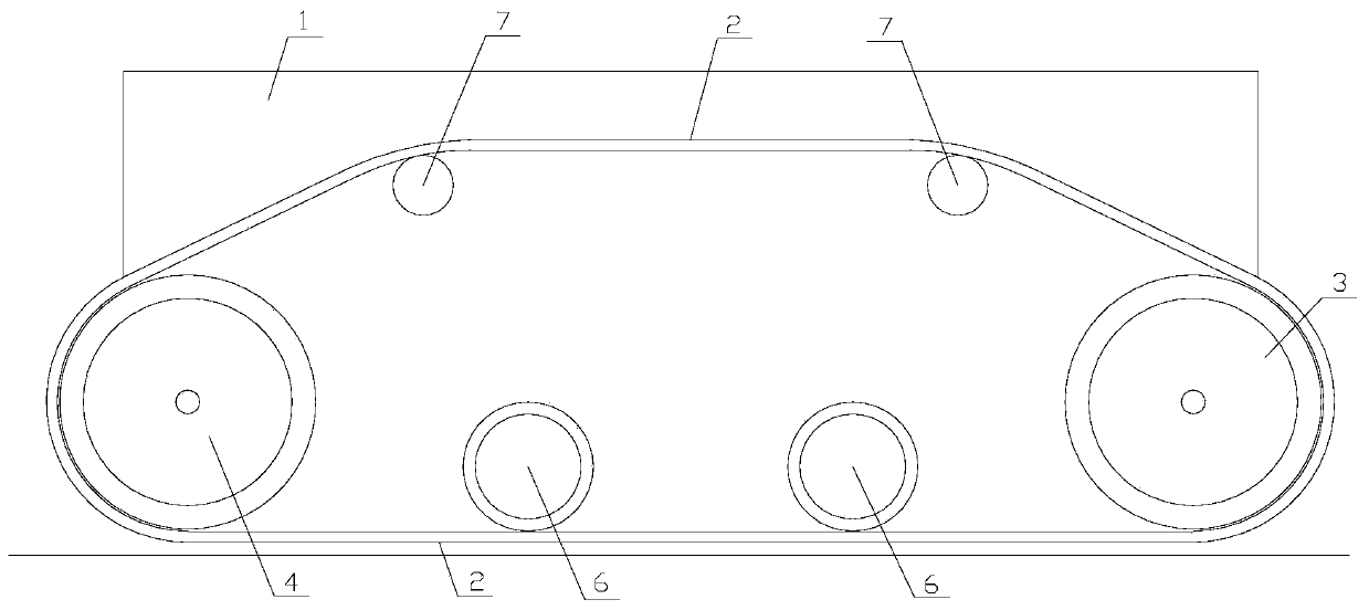
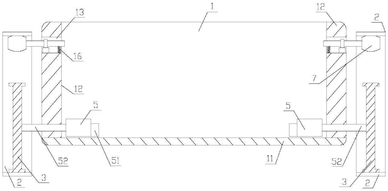
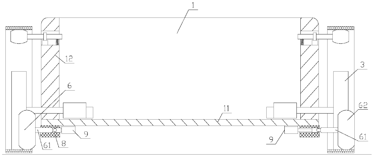
[0038] Such as Figure 1-6 As shown, a walking trolley of the present invention includes a storage frame 1, and the storage frame 1 includes a bottom plate 11 and four side plates 12, and a walking track 2 is respectively connected to the outside of the side plates 12 on both sides of the storage frame 1, and the two ends of the walking track 2 They are respectively sleeved on a front driving wheel 3 and a rear driving wheel 4, and the front driving wheel 3 and the rear driving wheel 4 are driven by the driving device 5 arranged on the storage frame 1, and several pressure rollers 6 are arranged on the inner side of the bottom of the walking track 2 The pressure roller 6 includes a rotating shaft 61, a roller 62 and a connecting piece 67. The roller 62 is sleeved on one end of the rotating shaft 61 and can rotate around the rotating shaft 61. Rotate, the connecting piece 67 is connected with the bottom of the storage frame 1 .

[0039] The outer surface of the roller 62 of th...

Embodiment 2

[0046] Such as Figure 1-6 As shown, a walking trolley of the present invention includes a storage frame 1, and the storage frame 1 includes a bottom plate 11 and four side plates 12, and a walking track 2 is respectively connected to the outside of the side plates 12 on both sides of the storage frame 1, and the two ends of the walking track 2 They are respectively sleeved on a front driving wheel 3 and a rear driving wheel 4, and the front driving wheel 3 and the rear driving wheel 4 are driven by the driving device 5 arranged on the storage frame 1, and several pressure rollers 6 are arranged on the inner side of the bottom of the walking track 2 The pressure roller 6 includes a rotating shaft 61, a roller 62 and a connecting piece 67. The roller 62 is sleeved on one end of the rotating shaft 61 and can rotate around the rotating shaft 61. Rotate, the connecting piece 67 is connected with the bottom of the storage frame 1 .

[0047] The outer surface of the roller 62 of th...


PUM


Abstract

The invention discloses a walking trolley. The walking trolley comprises an object placing frame, wherein the object placing frame comprises a base plate and four side plates, and walking caterpillarbands are connected to the outer sides of the side plates on the two sides of the object placing frame; the two ends of each walking caterpillar band are correspondingly arranged on a front driving wheel and a back driving wheel in a sleeving mode, and the front driving wheel and the back driving wheel are driven by a driving device arranged on the object placing frame; a plurality of pressure rollers are arranged on the inner sides of the bottoms of the walking caterpillar bands, and each pressure roller comprises a rotating shaft, a roller and a connecting piece; the roller is arranged at one end of the rotating shaft in a sleeving mode and can rotate by surrounding the rotating shaft, the connecting piece is movably connected to the other end of the rotating shaft, rotating shaft can rotate by surrounding the connecting piece, and the connecting piece is connected to the bottom of the object placing frame. The walking trolley can bear a certain weight of equipment and walks in mountain and hill physiognomy, and convey foundation pit excavation equipment to a designated construction site, and the construction efficiency of power transmission lines in mountain and hill areas is improved.

Description

technical field [0001] The invention relates to the field of electric power construction equipment, in particular to a walking trolley. Background technique [0002] In the foundation construction of power transmission lines in mountainous areas, in order to reduce vegetation damage and strengthen environmental protection, the foundation of iron towers mostly adopts manual excavation piles and excavated foundations. Compared with the large excavation foundation form, this foundation form has significant advantages in environmental protection, concrete maintenance, reduction of backfill operations, and full use of undisturbed soil properties, etc., and has become a common foundation type for transmission line projects. However, projects in mountainous and hilly areas, especially those in high-altitude areas, are located in plateaus with high altitudes and complex geology. Conventional foundation construction equipment is difficult to transport, labor-intensive, and dangerous....

Claims


Application Information

Patent Timeline
Patent Type & Authority Patents(China)
IPC IPC(8): B62D55/06B62D55/08B62D55/12B62D55/14
Inventor 李刚王建景文川武斌王毅刘新川李崇斌杨小斌
Owner SICHUAN POWER TRANSMISSION & TRANSFORMATION CONSTR
Why Eureka
Try Eureka