Ultra-silence underwater propeller

A propeller, ultra-quiet technology, applied in the direction of underwater ships, underwater operation equipment, ships, etc., can solve the problems of difficult to overcome mechanical noise, unfavorable military underwater ships lurking, reconnaissance and attack, etc., to achieve the goal of overcoming mechanical noise. Effect

Inactive Publication Date: 2019-01-29
杨雨斐
View PDF8 Cites 0 Cited by
  • Summary
  • Abstract
  • Description
  • Claims
  • Application Information

AI Technical Summary

Problems solved by technology

[0002] The traditional propeller propeller system, the engine will produce insurmountable mechanical noise due to high-speed rotation and mechanical transmission system, which is not conducive to the lurking, detection and attack of military underwater ships

Method used


Image

  • Ultra-silence underwater propeller
  • Ultra-silence underwater propeller

Examples


Embodiment Construction

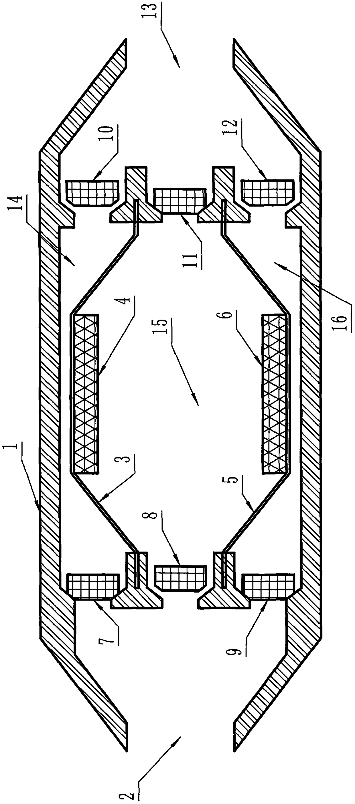
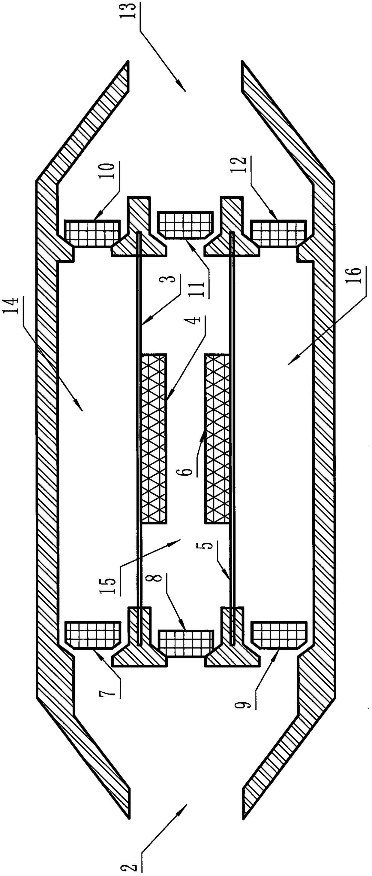
[0009] Such as figure 1 , figure 2 As shown, the present invention has a three-cavity structure and a one-way valve system that automatically controls the water flow in and out according to the movement of the cavities. There is a closed cavity between the water inlet 2 and the water outlet 13 of the shuttle-shaped housing 1, which is installed in the shuttle-shaped The rubber plate I 3 and the rubber plate II 5 on the shell 1 divide the cavity into three cavities: cavity I 14, cavity II 15 and cavity III 16, and a water inlet valve is installed at 2 water inlets of cavity I14 I 7, water outlet valve I 10 is installed at water outlet 13; water inlet valve II 8 is installed at the water inlet of cavity II 15, and water outlet valve II 11 is installed at the water outlet; water inlet valve III9 is ​​installed at the water inlet of cavity 1II16, and water outlet Install the water outlet valve III12. Electromagnet I 4 is installed on the rubber plate I 3, and electromagnet II 6...


PUM


Abstract

The invention discloses an ultra-silence underwater propeller. Mechanical noise generated by an engine and mechanical transmission cannot be generated. The ultra-silence underwater propeller comprisesa spindle-shaped shell, wherein a closed cavity is formed between a water inlet and a water outlet of the shell; the cavity is divided into three cavity bodies by two rubber plates installed on the shell; one-way valves are installed at water inlets and water outlets of the cavity bodies; and electromagnets are installed on the rubber plates.

Description

technical field [0001] The invention relates to a military underwater ship propulsion system, in particular to an ultra-quiet underwater propeller. Background technique [0002] In the traditional propeller propeller system, the engine will generate insurmountable mechanical noise due to high-speed rotation and mechanical transmission system, which is not conducive to the lurking, detection and attack of military underwater ships. Contents of the invention [0003] Aiming at the deficiencies of the prior art, the technical problem to be solved by the present invention is to provide an ultra-quiet underwater propeller, which does not generate mechanical noise generated by the engine and mechanical transmission. [0004] The basic idea of ​​the technical solution adopted by the present invention is: comprising a shuttle-shaped housing, a closed cavity is formed between the water inlet and the water outlet of the housing, and the two rubber plates installed on the housing sep...

Claims


Application Information

Patent Timeline
Patent Type & Authority Applications(China)
IPC IPC(8): B63G8/08
CPCB63G8/08
Inventor 杨雨斐
Owner 杨雨斐
Why Eureka
Try Eureka