
Synchronizing device, synchronizing device speed control system and vehicle

A technology of a synchronizing device and a vehicle, applied in the field of vehicles, can solve the problems that the synchronizing device does not have an energy recovery function, has a mechanical impact sound, and the speed regulation process is complicated, so as to improve the synchronization performance, reduce the secondary impact, and achieve good synchronization performance. Effect

Active Publication Date: 2020-12-18
GEELY CHANGXING AUTOMATIC TRANSMISSION CO LTD
View PDF10 Cites 0 Cited by
  • Summary
  • Abstract
  • Description
  • Claims
  • Application Information

AI Technical Summary

Problems solved by technology

[0003] An object of the present invention is to provide a synchronizing device that solves the problems of the existing synchronizing device with complex structure and mechanical impact sound
[0004] Another object of the present invention is to solve the problem that the synchronization device in the prior art does not have the energy recovery function
[0005] Another object of the present invention is to provide a synchronous device speed regulation system with the synchronous device, which solves the problem of complicated speed regulation process in the prior art

Method used


Image

  • Synchronizing device, synchronizing device speed control system and vehicle
  • Synchronizing device, synchronizing device speed control system and vehicle
  • Synchronizing device, synchronizing device speed control system and vehicle

Examples


Embodiment Construction

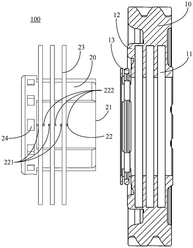
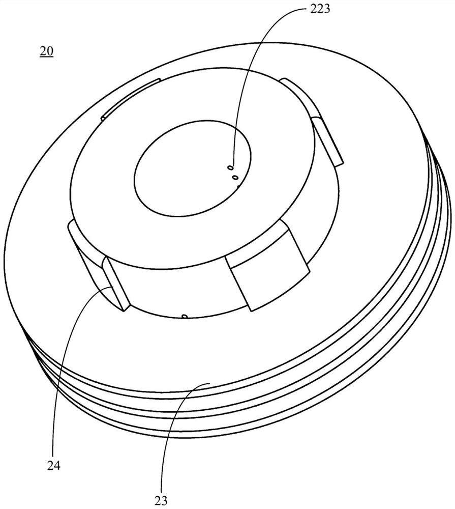
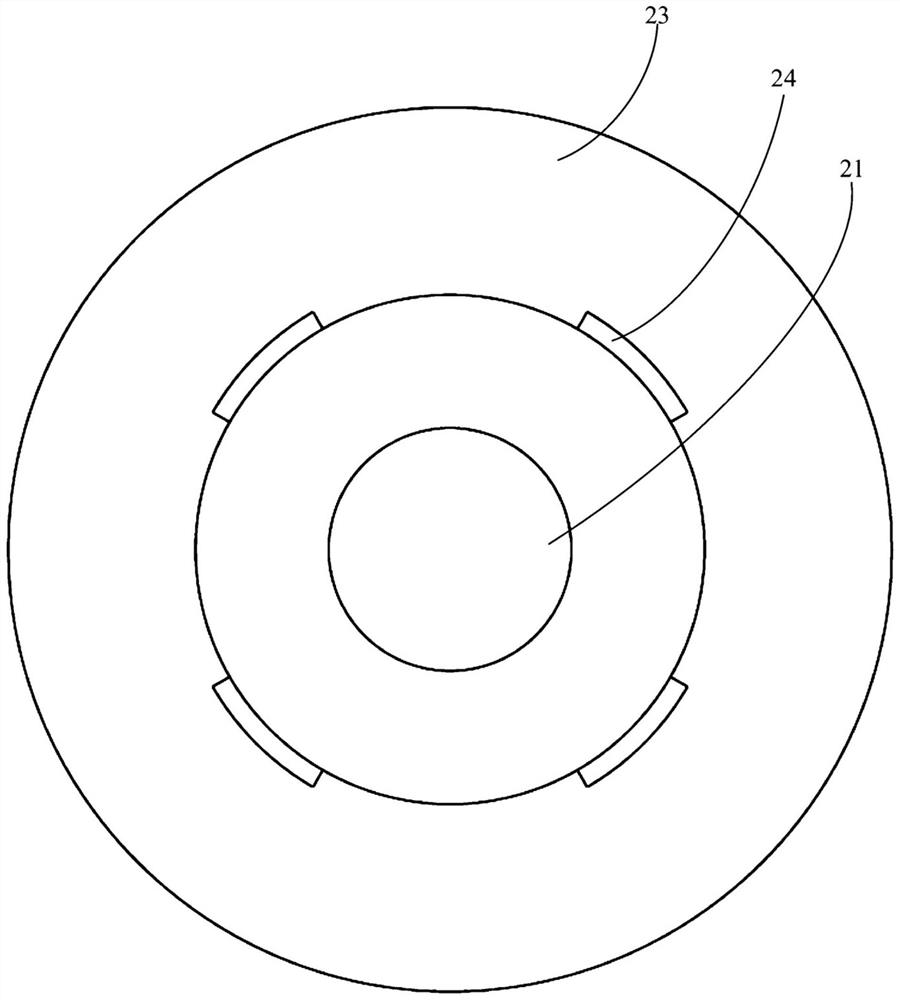
[0039] figure 1 It is a schematic structural diagram of the output shaft and the gear section of the synchronization device 100 according to an embodiment of the present invention. Specifically, the synchronization device 100 of this embodiment may include a gear 10 and an output shaft 20 . Wherein, the inner ring of the gear 10 is provided with a friction plate groove 11 . The output shaft 20 is provided with an oil inlet hole 21 with one end closed, and an oil outlet hole 22 communicating with the oil inlet hole 21 . A friction plate 23 is connected to the outer side of the output shaft 20 , and the oil outlet hole 22 can guide the hydraulic oil at the oil inlet hole 21 to the friction plate 23 . Wherein, the output shaft 20 is arranged on the inner ring of the gear 10, and the friction plate 23 is clamped at the groove 11 of the friction plate, and the hydraulic oil entering the output shaft 20 from the oil inlet hole 21 enters the groove of the friction plate from the oi...


PUM


Abstract

The invention provides a synchronizing device, a synchronizing device speed regulating system and a vehicle, and relates to the technical field of vehicles. The synchronizing device comprises a gear and an output shaft. A friction plate groove is formed in the inner ring of the gear. The output shaft is provided with an oil inlet hole with a sealed end and an oil outlet hole communicating with theoil inlet hole. The outer side of the output shaft is connected with a friction plate. The output shaft is arranged on the inner ring of the gear, and the friction plate is clamped on the friction plate groove. Hydraulic oil entering the output shaft from the oil inlet hole enters the friction plate groove from the oil outlet hole to push the friction plate, so that friction force is formed between the friction plate and the side wall of the friction plate groove, and the gear and the output shaft are synchronized. The synchronizing device is compact and simple in structure, and layout spaceis saved. According to the synchronizing device, mechanical devices (gear hubs, gear sleeves, soldered teeth and synchronizing rings) are omitted, secondary impacts are reduced, and mechanical noise of the end faces of the soldered teeth of a gear sleeving machine is avoided.

Description

technical field [0001] The invention relates to the technical field of vehicles, in particular to a synchronizing device, a speed regulating system of the synchronizing device and a vehicle. Background technique [0002] Today's automobile industry takes energy saving and emission reduction as the development direction. The transmission shifting system plays a key role in fuel economy, and the synchronizer affects the smoothness / comfort of shifting, thereby affecting the quality of shifting; especially shifting shock and NVH Noise index is one of the necessary conditions for customer evaluation; light weight, integration, miniaturization, intelligence, excellent space layout and reduction of shifting shock and NVH noise of shift system components have become the mainstream trend in the development process of dual clutch transmissions . The structure of the synchronizing device currently used is complex, the degree of integration and intelligence is low, and a mechanical imp...

Claims


Application Information

Patent Timeline
Patent Type & Authority Patents(China)
IPC IPC(8): F16D23/02F16H61/04
CPCF16D23/02F16H61/0403
Inventor 金磊于闯姚文博谭艳军林霄喆
Owner GEELY CHANGXING AUTOMATIC TRANSMISSION CO LTD
Learn More