Pneumatic static lateral pressure instrument and test method thereof

A static side pressure and pressure gauge technology, applied in the measurement of hydraulic/pneumatic force, etc., can solve problems such as insufficient accuracy, low test accuracy, and inaccurate force on soil samples, so as to improve work efficiency and test accuracy , the effect of uniform stress on the soil sample

Pending Publication Date: 2019-01-29
SHANGHAI MUNICIPAL ENG DESIGN INST GRP
View PDF0 Cites 2 Cited by
  • Summary
  • Abstract
  • Description
  • Claims
  • Application Information

AI Technical Summary

Problems solved by technology

The traditional stress-type static side pressure gauge has the following disadvantages: 1. When using a lever-type consolidation instrument to apply a graded load, it is necessary to manually control the time and move the weight, which is inefficient; 2. When applying axial pressure, due to the compression deformation of the soil It will cause the lever to be out of balance. In order to keep the lever in balance, it is necessary to manually adjust the lever, otherwise the force on the soil sample will be inaccurate; 3. The lever-type consolidation instrument has been used for a long time, and it is difficult to adjust the balance of the lever due to mechanical wear and tear; 4. When using a syringe to pump out the water in the pressurized chamber, it is difficult to prevent the gas from entering the pressurized chamber of the pressure vessel on the static side due to the poor sealing of the junction between the s

Method used


Image

  • Pneumatic static lateral pressure instrument and test method thereof
  • Pneumatic static lateral pressure instrument and test method thereof
  • Pneumatic static lateral pressure instrument and test method thereof

Examples


Embodiment Construction

[0025] The invention will be specifically described below according to the drawings and specific embodiments of the invention.

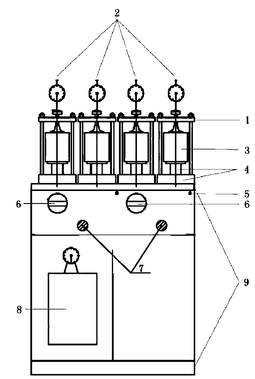
[0026] Such as figure 1 As shown, a pneumatic static side pressure instrument includes a cabinet-type operating table 9, an air compressor 8 is installed in the cabinet-type operating table 9, and an air source solenoid valve 5 is installed on the operation panel of the cabinet-type operating table 9, plus Pressure control device 6, and pressure regulating valve 7, the top of the cabinet type operation table 9 is provided with a pressurized base 4 and a piston guide rod matched with it, the pressurized base 4 is provided with a fixed frame 1, and a stationary side The pressure gauge container 3, the piston guide rod is located at the bottom of the static side pressure gauge container 3, and the displacement sensor 2 connected to the static side pressure gauge container 3 is installed on the top of the fixed frame.

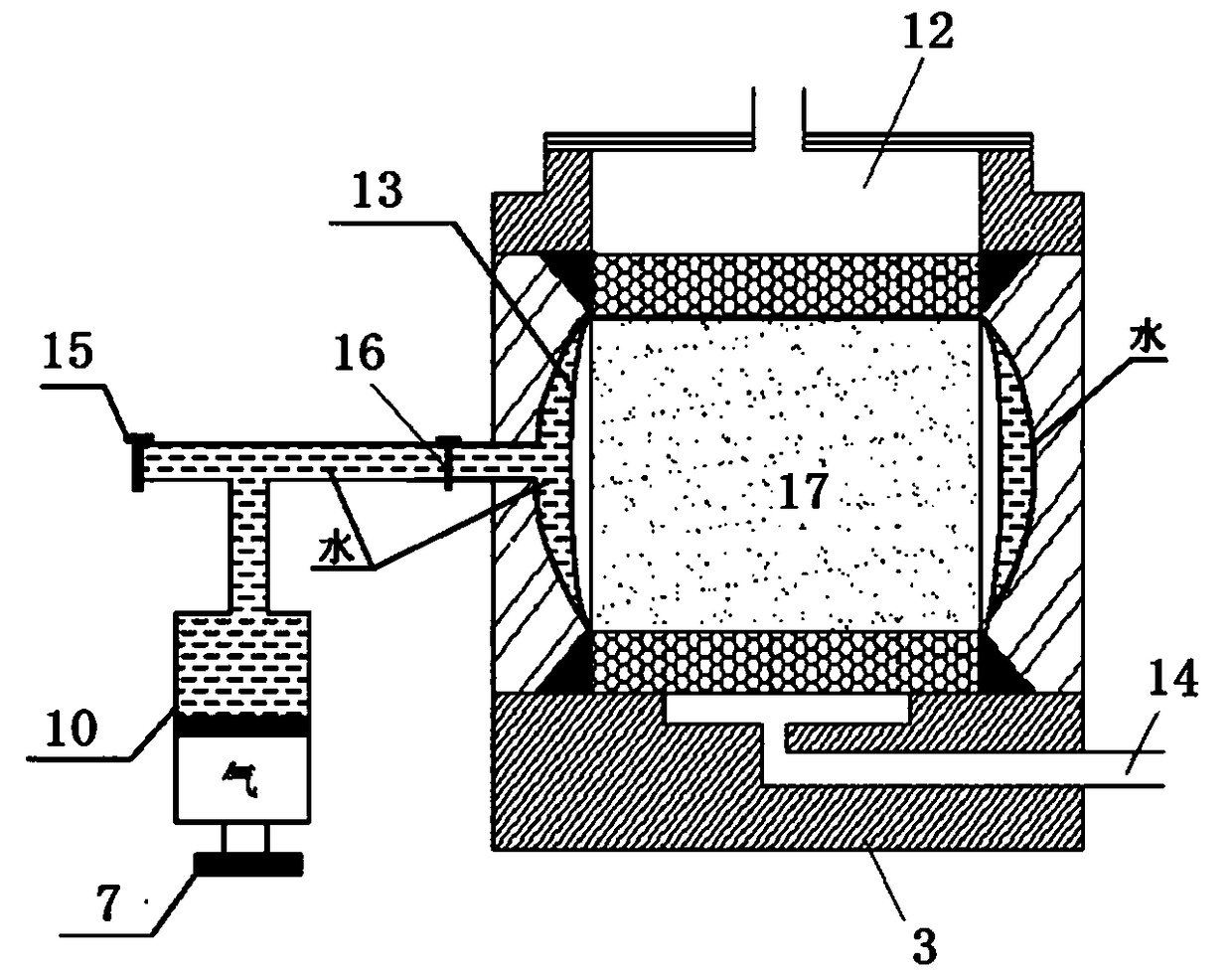
[0027] figure 2 Shown is a sche...


PUM


Abstract

The invention discloses a pneumatic static lateral pressure instrument, which comprises a static lateral pressure instrument container, a vacuum pressure regulating cylinder and a pressurizing base, wherein the pressurizing base is internally provided with a pressure chamber, the bottom of the pressure chamber is connected with an air compressor, the pressure chamber is internally provided with apressure film depressing downward, there is a piston guide rod above the pressure film, and the piston guide rod is located at the bottom of the static lateral pressure instrument container. The pneumatic static lateral pressure instrument adopts pneumatic pressurizing equipment, can automatically load in a grading manner and can set the pressurizing time according to requirements. The pneumatic static lateral pressure instrument is more stable compared with manual weight loading, the soil sample is also uniformly stressed, and the test accuracy is improved. The pneumatic static lateral pressure instrument regulates the water body in the container by adopting a vacuum pressure regulating cylinder via a manual pressure regulating valve, thereby effectively preventing a gas from entering thepressure chamber of the container, ensuring the volume of water in the sealed pressure chamber to be constant in the testing process, guaranteeing the accuracy of pressure conduction, and improving the test accuracy.

Description


Claims


Application Information

Patent Timeline
Owner SHANGHAI MUNICIPAL ENG DESIGN INST GRP
Why Eureka
Try Eureka