
Flyback power converter circuit and high voltage start-up circuit thereof

A technology of power supply circuit and high-voltage start-up, applied in the direction of electrical components, output power conversion devices, etc., can solve the mismatch of the primary side control circuit, the inability to freely control the conduction state of the high-voltage start-up switch QD, increase the cost and circuit size, etc. question

Inactive Publication Date: 2019-01-29
RICHTEK TECH
View PDF5 Cites 0 Cited by
  • Summary
  • Abstract
  • Description
  • Claims
  • Application Information

AI Technical Summary

Problems solved by technology

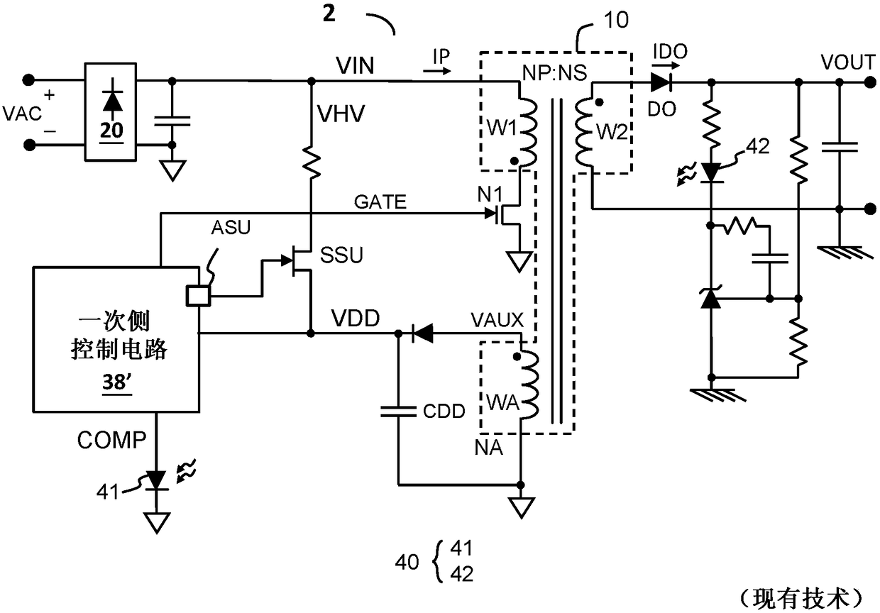
[0005] figure 2 The disadvantage of the prior art shown in , is that the primary-side control circuit 38' needs a dedicated pin ASU and a control function to control the high-voltage startup switch SSU. Due to the increase in the number of pins, generally speaking, SOP8 and other higher Larger packages, which increase cost and circuit size
In addition, inventory management is not easy for suppliers or their customers who provide primary side control circuits 38 and 38' at the same time.
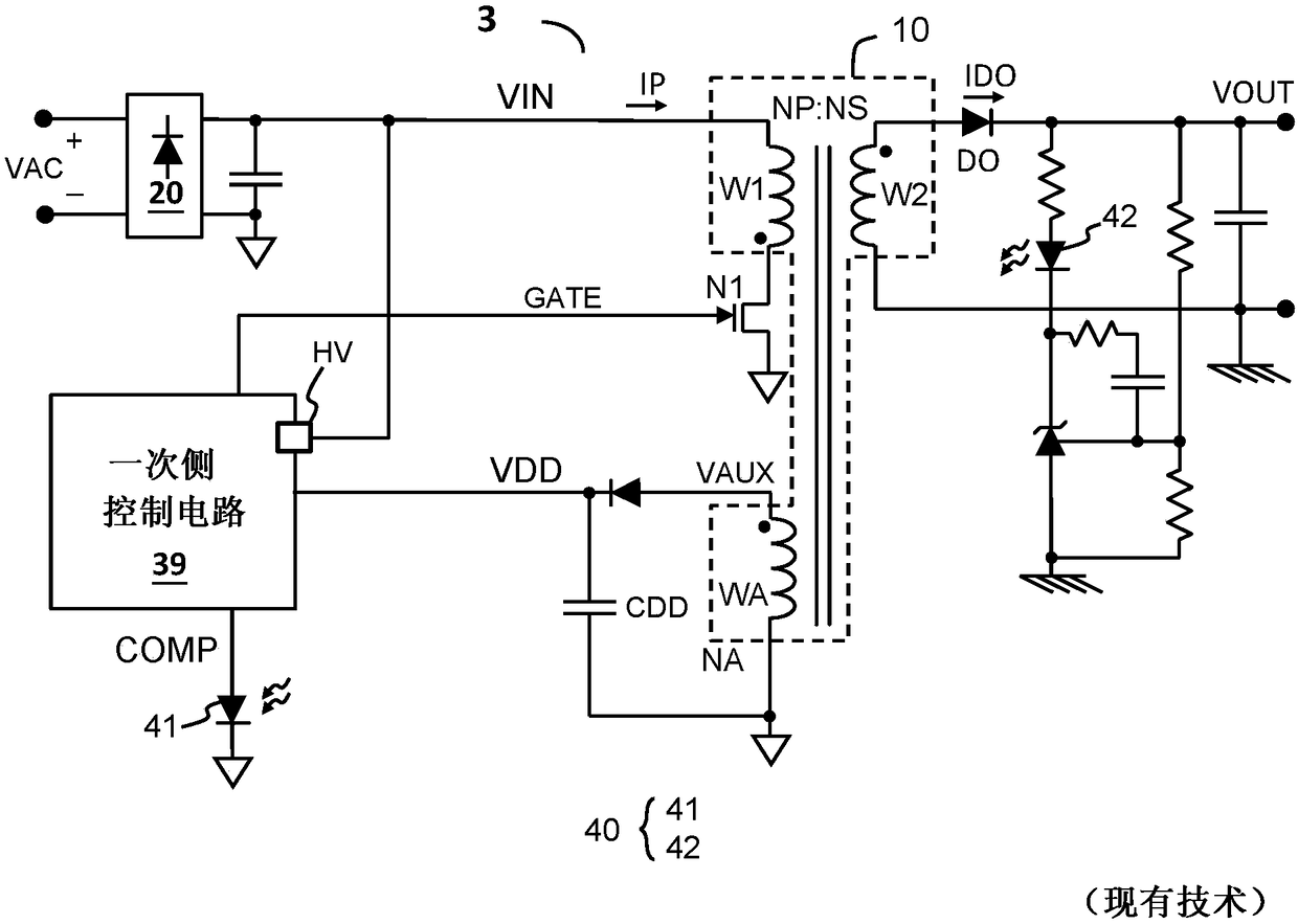
[0006] image 3 Another prior art flyback power supply circuit (flyback power supply circuit 3) is shown, wherein the flyback power supply circuit 3 integrates a high-voltage start-up switch SSU into a primary side control circuit 39, due to the number of pins Increase (such as pin HV shown in the figure) and integration of the high voltage start switch and its control, thus also increasing the cost and the size of the circuit, especially will cause difficulties in inventory management
[0007] Figure 4 Among them, the US patent application US 2017 / 0005583 A1 shows another prior art flyback power supply circuit (flyback power supply circuit 500), wherein the flyback power supply circuit 500 shares the primary side control circuit The FB pin of the 501 is used to control the external high-voltage start switch QD. Since the FB pin is a shared pin, the high-voltage start switch QD cannot freely control its conduction state. It is operated during power conversion, so if there is a large external capacitive load, it is easy to encounter the problem that it cannot be turned on smoothly
[0008] In addition, in the aforementioned prior art, the external high-voltage starting switch may come from different suppliers, therefore, the problem of mismatching with the primary side control circuit may also occur

Method used


Image

  • Flyback power converter circuit and high voltage start-up circuit thereof
  • Flyback power converter circuit and high voltage start-up circuit thereof
  • Flyback power converter circuit and high voltage start-up circuit thereof

Examples


Embodiment Construction

[0032] The drawings in the present invention are all schematic diagrams, mainly intended to show the coupling relationship between various circuits and the relationship between various signal waveforms. As for the circuits, signal waveforms and frequencies, they are not drawn to scale.

[0033] see Figure 5A , shown in the figure is an embodiment of the flyback power supply circuit of the present invention (flyback power supply circuit 5A), the flyback power supply circuit 5A includes a transformer 10, a primary side switch N1, and a high-voltage starting circuit 20 , and the primary side control circuit 30. The transformer 10 has a primary winding W1, a secondary winding W2, and an auxiliary winding WA, wherein the primary winding W1 is used to receive an input voltage VIN, and the secondary winding W2 is used to generate an output voltage VOUT. In one embodiment, the input voltage VIN can be generated by rectifying the AC input signal VAC by the rectification circuit 50 . ...


PUM


Abstract

A flyback power converter includes a transformer having an auxiliary winding for generating an auxiliary voltage and providing a supply voltage on a supply node; a primary side controller circuit which is powered by the supply voltage from the supply node; and a high voltage (HV) start-up circuit. The HV start-up circuit is coupled to an high voltage signal through a HV input terminal and generates the supply voltage through a supply output terminal, wherein when the supply voltage does not exceed a start-up voltage threshold, a HV start-up switch conducts the HV input terminal and the supplyoutput terminal to provide the supply voltage, and when the supply voltage exceeds a start-up voltage threshold, the HV start-up switch is OFF. The HV start-up circuit and the primary side controllercircuit are packaged in two separate integrated circuit packages respectively.

Description

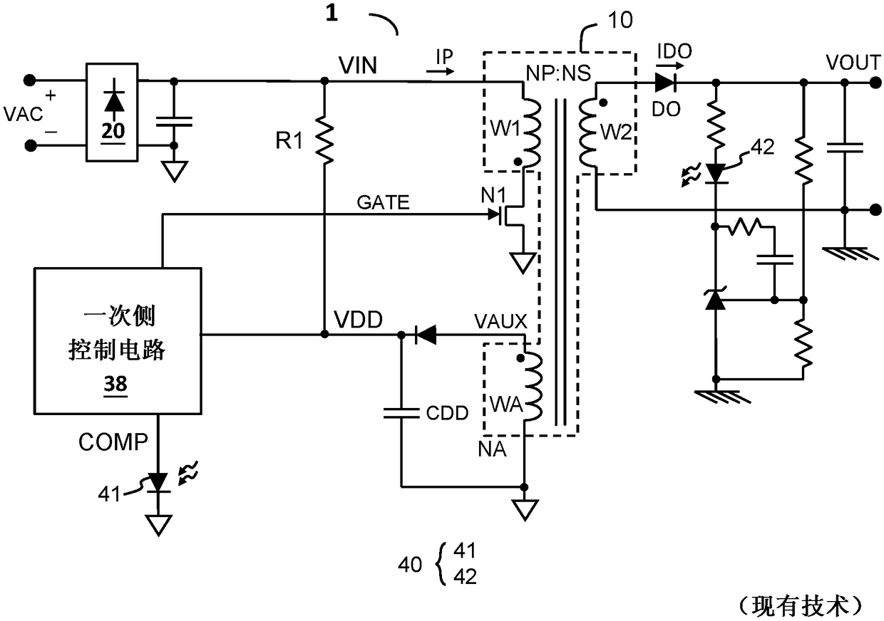
technical field [0001] The invention relates to a flyback power supply circuit, in particular to a flyback power supply circuit with a high-voltage starting circuit. The invention also relates to a high-voltage start-up circuit used in a flyback power supply circuit. Background technique [0002] Prior applications related to this application include: US patent application US 2017 / 0005583 A1 and Chinese patent application CN 106329961 A. [0003] figure 1 A prior art flyback power supply circuit (flyback power supply circuit 1) is shown, wherein the flyback power supply circuit 1 includes a transformer 10, a primary side switch N1, and a primary side control circuit 38, wherein the auxiliary winding WA is used for generating a supply voltage VDD as a power source for the primary side control circuit 38 . In this prior art, the primary side control circuit 38 can generally use a SOT23-6 type package to reduce costs, and VDD is charged through an external resistor R1. After...

Claims


Application Information

Patent Timeline
Patent Type & Authority Applications(China)
IPC IPC(8): H02M1/36
CPCH02M1/36
Inventor 唐健夫陈曜洲林梓诚林昆馀萧立扬赖勇志
Owner RICHTEK TECH
Learn More