
Collecting apparatus for reactor, and reactor

A collection device and reactor technology, applied in feeding devices, chemical instruments and methods, chemical/physical/physical-chemical processes, etc., can solve the problems of high operation difficulty and cost, mixing catalyst, and difficult operation, etc., and achieve improvement Fluid velocity distribution, uniform fluid velocity distribution, and the effect of increasing the filling amount

Active Publication Date: 2019-02-01
CHINA PETROLEUM & CHEM CORP +2
View PDF8 Cites 0 Cited by
  • Summary
  • Abstract
  • Description
  • Claims
  • Application Information

AI Technical Summary

Problems solved by technology

[0003] At present, there are several problems in the outlet collector in industrial production: (1) The scale of the fixed bed reactor tends to be large-scale (with a diameter of more than 4-5m), and the size of the outlet collector installed in the bottom head of the reactor also varies with the size of the outlet collector. The increase in volume will bring a lot of inconvenience to its manufacture, transportation and installation
The large-volume outlet collector is limited by the size of the reactor inlet when it enters the reactor, and because of its heavy weight, it needs to be hoisted by a crane during the installation process, which makes the operation difficult
(2) At present, bolts and other fasteners are used to connect the outlet collector and the head, which is cumbersome to install and requires operators to work in a closed space for a long time, and the operation risk is high
The catalyst particles are broken in the reactor, and the broken catalyst will block the wire mesh, causing partial blockage of the outlet collector and even further reaction of the product to produce coking
In addition, under the high temperature and pressure in the reactor and the friction of the catalyst, there is also a risk of damage to the wire mesh. On the one hand, the damaged position will leak the catalyst, causing the catalyst to be mixed into the reaction product stream; Debris can further cause clogging of the outlet collector
Once local damage or blockage occurs, the entire outlet collector must be removed for replacement, which is difficult and expensive to operate
(4) The cylinder structure of the existing cylindrical outlet collector occupies a large space, occupying a part of the catalyst filling space, and the product accumulates near it, affecting the distribution of the upper liquid

Method used


Image

  • Collecting apparatus for reactor, and reactor
  • Collecting apparatus for reactor, and reactor
  • Collecting apparatus for reactor, and reactor

Examples


no. 1 example

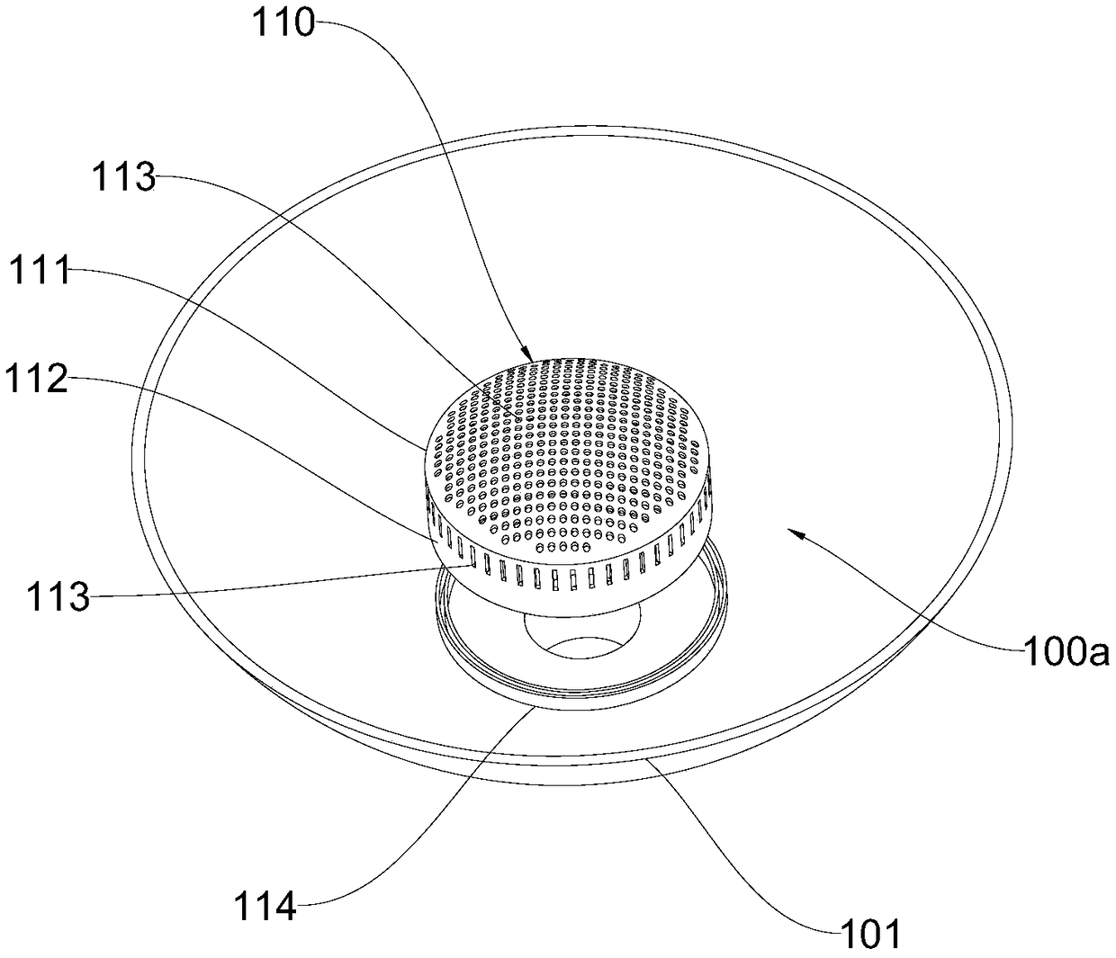
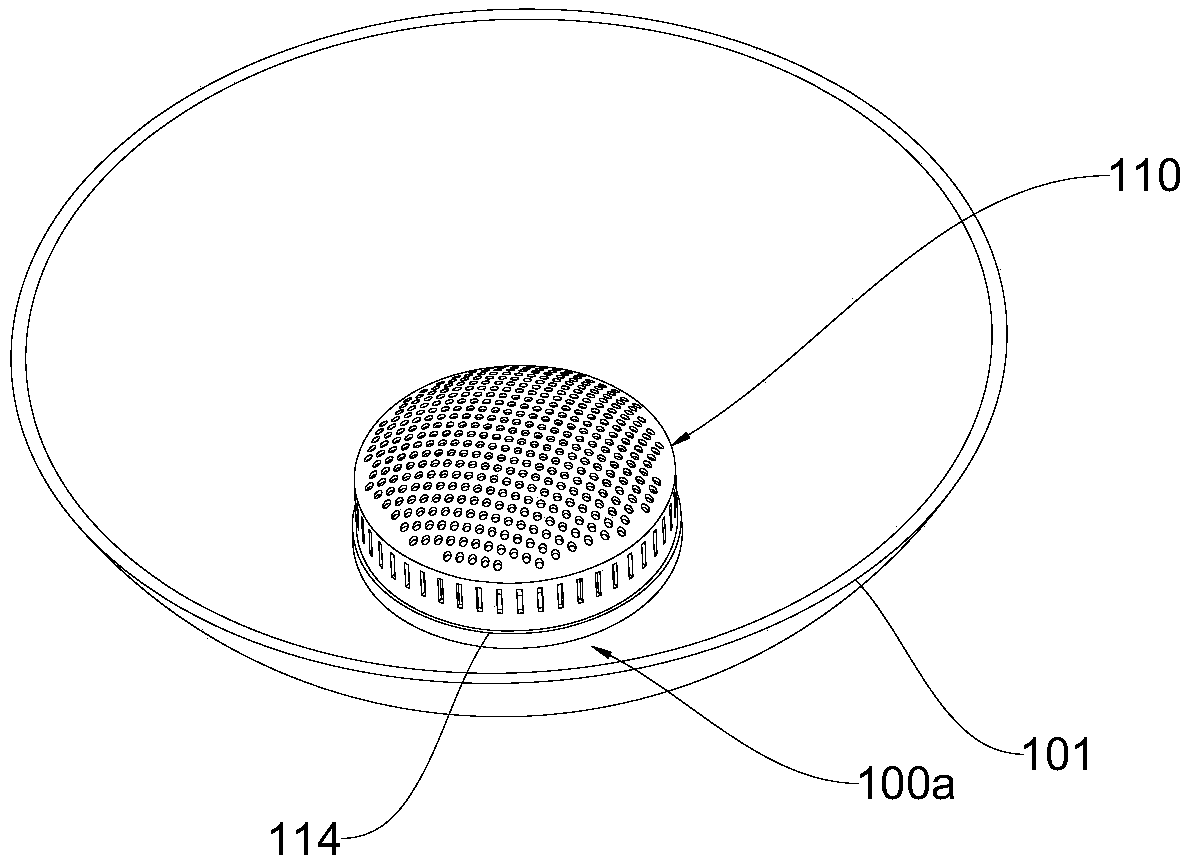
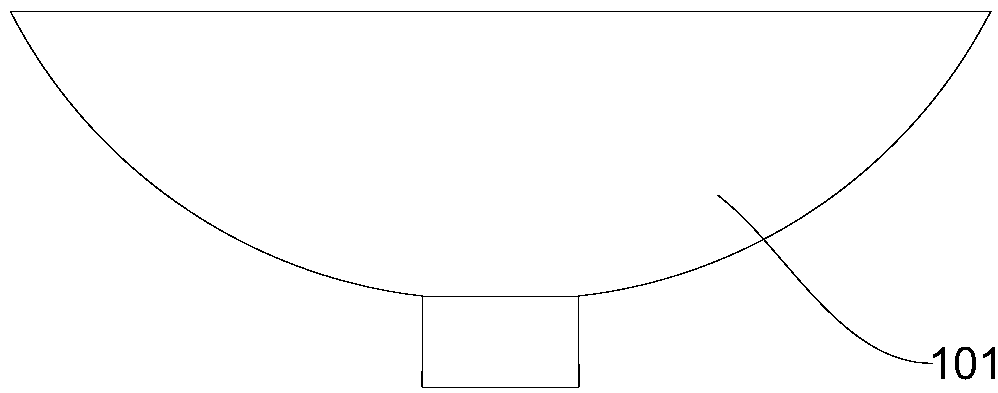
[0038] Please combine Figure 1-Figure 5 The embodiment of the present invention provides a collection device 100a for a reactor, which is installed on the bottom head 101 of the reactor, and is mainly used for isolating the catalyst and allowing the liquid material to pass through the collection device 100a and then output from the bottom outlet of the reactor.

[0039] Specifically, the collection device 100a includes a collection cover 110, the collection cover 110 includes a top end surface 111 and a side end surface 112, the top of the side end surface 112 is connected to the edge of the top end surface 111, and the bottom of the side end surface 112 is connected to the bottom end surface. The inner wall of 101 is connected, and the collection cover 110 is provided with a flow channel for liquid material circulation (as shown in the liquid inlet hole 113); the top end surface 111 of the collection cover 110 is arc-shaped, and the convex surface position of the top end surf...

no. 2 example

[0046] Please refer to Figure 6-Figure 8 , the implementation principle and technical effects of the device provided by the embodiment of the present invention are the same as those of Embodiment 1. For brief description, for the parts not mentioned in this embodiment, reference may be made to the corresponding content in Embodiment 1. The collection device provided in this embodiment can be adapted to larger reactors. Generally speaking, reactors with a diameter greater than 3m can adopt the block combination method provided in this embodiment.

[0047] Specifically, the collection cover 110 is spliced ​​by a plurality of spliced ​​covers 115, and each spliced ​​cover 115 includes a spliced ​​top end face 116 and a spliced ​​side end face 117, and a plurality of spliced ​​top end faces 116 are spliced ​​into a top end face 111. Two splicing side end faces 117 are spliced ​​into the side end face 112 of the collecting cover 110; The method of splicing multiple splicing cover...


PUM


Abstract

The invention provides a collecting apparatus for a reactor, and the reactor, and relates to the technical field of chemical equipment. The collecting apparatus for the reactor is arranged on the bottom sealing head of the reactor, and comprises a collecting cover body, wherein the collecting cover body comprises a top end surface and a side end surface, the top portion of the side end surface isconnected to the edge of the top end surface, the bottom portion of the side end surface is connected to the inner wall of the bottom sealing head, the collecting cover body is provided with a circulation pore channel for circulating a liquid material, the top end surface of the collecting cover body is arc-shaped, and the convex surface of the top end surface is higher than the top portion of theside end surface. The reactor comprises the collecting apparatus for the reactor, wherein the collecting apparatus is arranged on the inner wall of the bottom sealing head of the reactor, such that the catalyst can be effectively isolated, and the fluid above the collecting apparatus has the uniform velocity distribution.

Description

technical field [0001] The invention relates to the technical field of chemical equipment, in particular to a collection device for a reactor and a reactor. Background technique [0002] In the gas-solid or gas-liquid-solid heterogeneous catalytic reactions involved in petroleum refining and chemical production, such as hydrocracking of heavy oil, hydrofinishing of lubricating oil, hydrofining of naphtha, coal tar Hydrogenation, hydrogenation of wax fat to prepare fatty alcohol and hydrogenation of butynediol to butanediol are commonly used in fixed bed reactors. In this type of processing, the reaction materials flow in from the top of the fixed bed reactor, and after being shaped by the inlet diffuser, they fall on the distribution plate. It flows downward and finally flows out from the outlet collector at the bottom of the reactor. The outlet collector plays a supporting role for the catalyst, and the bottom is connected with the outlet pipeline, allowing the gas-liquid...

Claims


Application Information

Patent Timeline
Patent Type & Authority Applications(China)
IPC IPC(8): B01J19/00B01J4/00
CPCB01J4/001B01J19/0053
Inventor 李小婷李立权陈崇刚陈强蔡连波盛维武裘峰赵晓青赵颖韩旭辉郭为民刘茂增扈文峰冯勇陈超陈险峰高巧丽崔月辉
Owner CHINA PETROLEUM & CHEM CORP
Learn More