Hollow near-forming forging method of large MW wind power main shaft

A wind power spindle, near-molding technology, applied in mechanical equipment, engine components, metal processing equipment, etc., can solve the problems of low production cost and small inner hole at the small end.

Inactive Publication Date: 2019-02-01
SHANDONG LAIWU JINLEI WIND POWER TECH
View PDF6 Cites 9 Cited by
  • Summary
  • Abstract
  • Description
  • Claims
  • Application Information

AI Technical Summary

Problems solved by technology

The invention solves the problem of wind power spindles with small head-end blind holes through the punching and back-extrusion technology of the inner hole; at the same time, it solves the problem of the production of wind power spindles with very small inner holes at the small head end, and greatly reduces the waste of raw materials in the production process , low production cost

Method used


Image

  • Hollow near-forming forging method of large MW wind power main shaft
  • Hollow near-forming forging method of large MW wind power main shaft
  • Hollow near-forming forging method of large MW wind power main shaft

Examples


Embodiment Construction

[0020] In order to make the object, technical solution and advantages of the present invention more clear, the present invention will be further described in detail below in conjunction with the examples. It should be understood that the specific embodiments described here are only used to explain the present invention, not to limit the present invention.

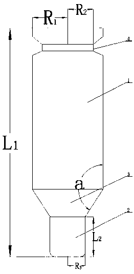
[0021] The forging method of the hollow near-forming of the large MW wind power main shaft includes the following specific steps:

[0022] Step 1: Heating the steel ingot to 1200-1250°C, keeping it warm, then chamfering, removing the spout, upsetting, drawing and cutting;

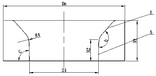
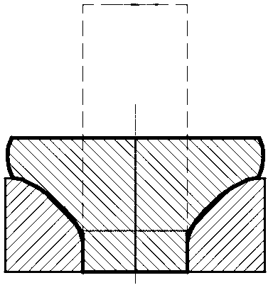
[0023] The second step: heat the steel ingot after the first step to 1200-1250°C and keep it warm, such as image 3 shown, and then upsetting with a special anti-extrusion leakage disc ( figure 2 ), after upsetting with a drain plate, such as Figure 4 As shown, then punch down to a certain height through a special punching mandrel, such as Figure ...


PUM

PropertyMeasurementUnit
heightaaaaaaaaaa
radiusaaaaaaaaaa
radiusaaaaaaaaaa

Abstract

The invention discloses a hollow near-forming forging method of a large MW wind power main shaft. The method is characterized by comprising the following specific steps that 1, a steel ingot is heatedto 1200-1250 DEG C, heat preservation is carried out, then chamfering is carried out, water removing and upsetting are carried out, and blanking is carried out after the steel ingot is pulled out; 2,the steel ingot subjected to the first step is heated to 1200-1250 DEG C, heat preservation is carried out, then upsetting is carried out by adopting a special anti-extrusion leakage disc, then the hole is punched downwards to a certain height through a special punching core rod, and then the special punching core rod is used for drawing to a certain size; 3, the steel ingot subjected to the second step is heated to 1200-1250 DEG C, heat preservation is carried out, then upsetting is carried out by adopting a special anti-extrusion leakage disc, then the hole is punched downwards to a certainheight through a special punching core rod, and then a flange is printed out; and 4, the steel ingot subjected to the third step is heated to 1150-1250 DEG C, heat preservation is carried out, then locally upsetting the flange through the leakage disc, and finally the flange is formed and finished to obtain a finished product. According to the method, the problem that the small-head-end inner hole is very small in wind power main shaft production is solved, the waste of raw materials in the production process is greatly reduced, and the production cost is low.

Description

technical field [0001] The invention relates to the technical field of wind power, specifically a hollow near-forming forging method for a large MW wind power main shaft. Background technique [0002] With the rapid development of wind power generation, the models of wind turbines tend to be larger, and the specifications of wind power main shafts are also becoming larger. Large MW wind power main shafts such as 5 MW and 6 MW are constantly being introduced. The large MW wind power main shaft is mainly divided into three parts, the flange, the shaft body, and the inner hole; and the inner hole is mostly irregular in shape, the inner hole near the flange end is large, and the diameter of the inner hole becomes smaller toward the shaft body. At present, forging is basically solid forging, and the inner hole is completed by subsequent machining. However, with the continuous increase of the inner hole, more and more materials are removed from the center during the machining of ...

Claims


Application Information

Patent Timeline
Patent Type & Authority Applications(China)
IPC IPC(8): B21J5/08B21J5/10B21K1/06
CPCB21J5/002B21J5/08B21J5/10B21K1/063
Inventor 廉荣光李新生时乐智陈文全
Owner SHANDONG LAIWU JINLEI WIND POWER TECH
Why Eureka
Try Eureka