
Drilling equipment for machining

A drilling equipment and machining technology, which is applied in metal processing equipment, drilling/drilling equipment, boring/drilling and other directions, can solve the problems of difficulty in realizing automatic drilling of mechanical parts and high labor expenditure of staff. Achieve the effect of avoiding drilling deviation, improving stability and increasing friction

Inactive Publication Date: 2019-02-01
盐城新时代智能检测设备制造厂
View PDF0 Cites 5 Cited by
  • Summary
  • Abstract
  • Description
  • Claims
  • Application Information

AI Technical Summary

Problems solved by technology

[0004] The purpose of the present invention is to make up for the deficiencies of the prior art, and to provide a drilling device for mechanical processing, which has the advantages of being able to realize automatic drilling of mechanical parts and reducing the labor expenditure of the staff, and solves the problem of the existing drilling equipment. It is difficult for the hole machine to realize the automatic drilling operation of mechanical parts, and the problem of high labor expenditure of the staff

Method used


Image

  • Drilling equipment for machining
  • Drilling equipment for machining
  • Drilling equipment for machining

Examples


Embodiment Construction

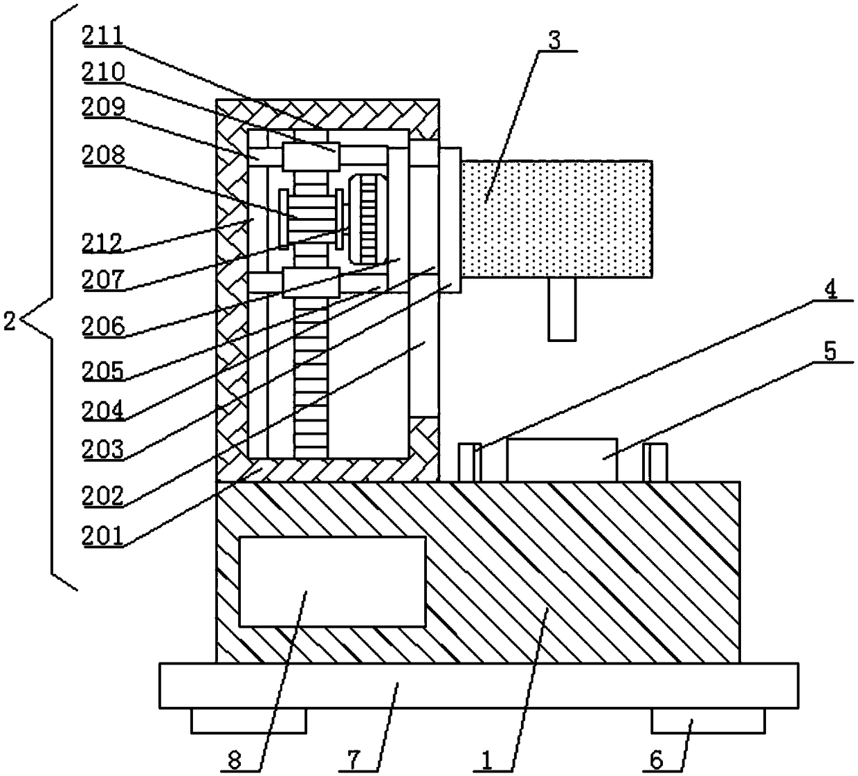
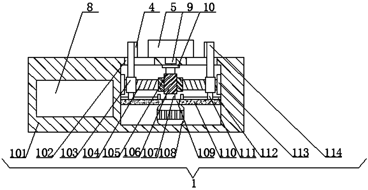
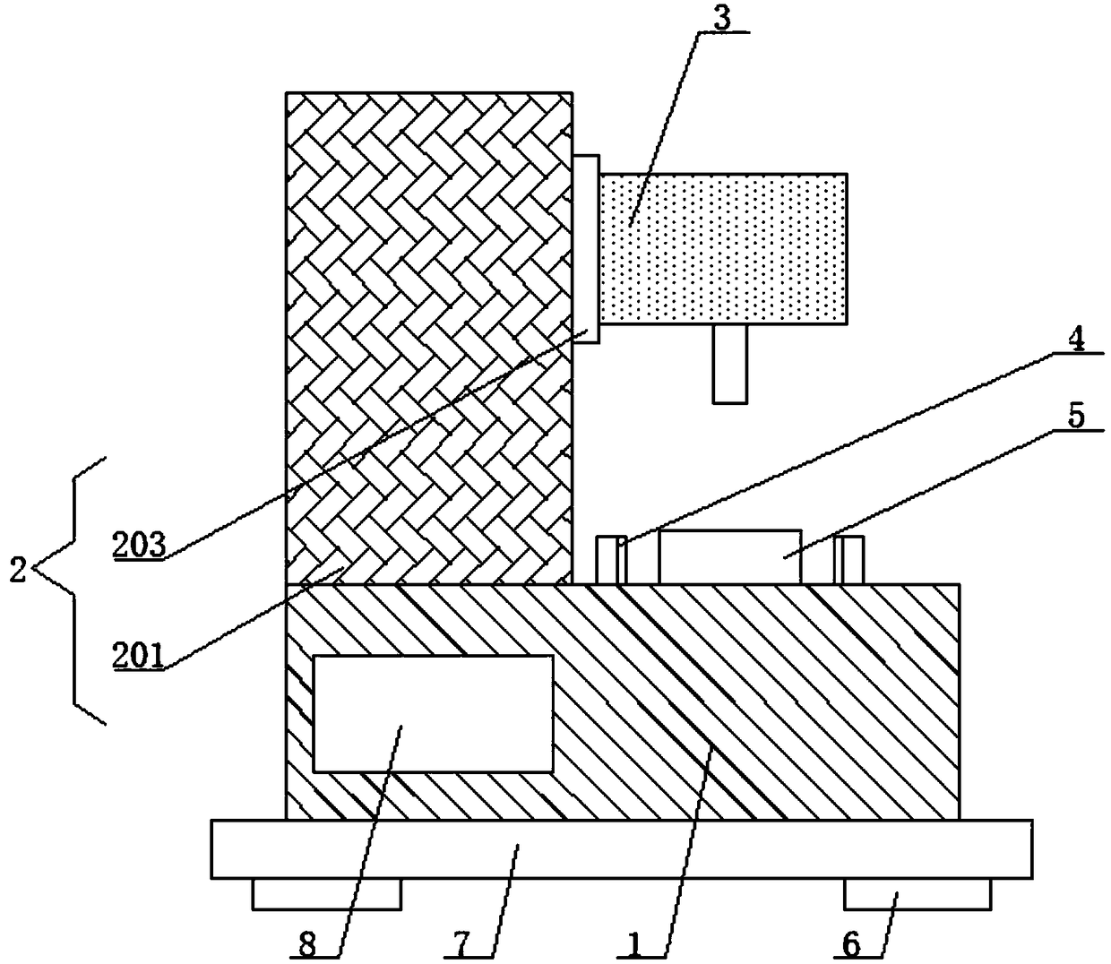
[0021] like Figure 1-4 As shown, the present invention provides a technical solution: a drilling equipment for machining, comprising a clamping mechanism 1, the bottom surface of the clamping mechanism 1 is fixedly connected with a fixing seat 7, and the four corners of the bottom surface of the fixing seat 7 are There are anti-skid pads 6 fixedly connected, and the bottom surface of each anti-skid pad 6 is provided with anti-skid lines 11, which can effectively increase the friction between the bottom surface of the fixed seat 7 and the ground, improve the overall stability of the drilling equipment, and avoid the use of Due to external force, the drilling equipment falls down, causing damage to the drilling equipment. The lifting mechanism 2 is installed on the upper surface of the clamping mechanism 1, the drilling machine body 3 is installed on the left side of the lifting mechanism 2, and the upper surface of the clamping mechanism 1 is installed. A workpiece body 5 is p...


PUM


Abstract

The invention discloses drilling equipment for machining, and relates to the technical field of machining. The drilling equipment comprises a clamping mechanism, and the bottom face of the clamping mechanism is fixedly connected with a fixed base. According to the drilling equipment for machining, by arranging an anti-sliding mat and anti-sliding grains, friction force between the bottom face of the fixed base and the ground can be effectively increased, the overall stability of the drilling equipment is improved, and it is avoided that in the use process, the drilling equipment topples due toexternal force, and consequently the drilling equipment is damaged. By arranging a second forward and backward rotating motor, a gear, a toothed bar, a movable plate, a second sliding block and a moving plate, the second forward and backward rotating motor drives the gear to rotate, and the second forward and backward motor drives the movable plate to move downwards; the movable plate drives themoving plate to move downwards through the second sliding block, so that a drilling machine body moves downwards, and automatic drilling work on a workpiece body is achieved; automatic drilling work of a mechanical accessory can be achieved overall, and the labor expenditure of workers is reduced

Description

technical field [0001] The invention relates to the technical field of machining, in particular to a drilling device for machining. Background technique [0002] Machining refers to the process of changing the dimensions or properties of a workpiece through a mechanical device. According to the difference in processing methods, it can be divided into cutting processing and pressure processing. [0003] Drilling machines are necessary for the drilling of mechanical parts, but the existing drilling machines are often simpler in structure, and it is difficult to realize automatic drilling of mechanical parts. Only by fixing the accessories with one hand and operating the drilling machine with the other hand can the drilling operation of the accessories be realized. This method not only has high labor expenditure for the staff, but also has low work efficiency. For this reason, we provide a machining Drilling equipment to solve this problem. SUMMARY OF THE INVENTION [0004...

Claims


Application Information

Patent Timeline
Patent Type & Authority Applications(China)
IPC IPC(8): B23B39/00B23B47/18B23B47/26B23Q3/06B23Q11/00
CPCB23B39/00B23B47/26B23Q3/06B23Q5/48B23Q11/00
Inventor 吕年标
Owner 盐城新时代智能检测设备制造厂
Learn More