Feeding device of exposure machine

A technology of an exposure machine and a power device, which is applied to the field of the feeding device of the exposure machine, can solve the problems of complex, irregular manual placement and unreasonable feeding of the exposure machine, etc., and achieves the effect of a reasonable structure.

Pending Publication Date: 2019-02-01
JIANGSU GIS LASER TECH INC
View PDF0 Cites 14 Cited by
  • Summary
  • Abstract
  • Description
  • Claims
  • Application Information

AI Technical Summary

Problems solved by technology

[0002] The current exposure machine for mobile phone cases includes an exposure main unit, on which a bottom plate is placed, and then the mobile phone case is manually placed on the bottom plate, and then exposed through the exposure main unit, because manual placement is prone to irregular situations, At this time, it is very difficult for the exposure machine to detect the edge of the mobile phone case, the calculation is complicated, and the manual operation is more complicated, which requires a lot of labor. Therefore, the current exposure machine is unreasonable for loading materials.

Method used


Image

  • Feeding device of exposure machine
  • Feeding device of exposure machine
  • Feeding device of exposure machine

Examples


Embodiment 1

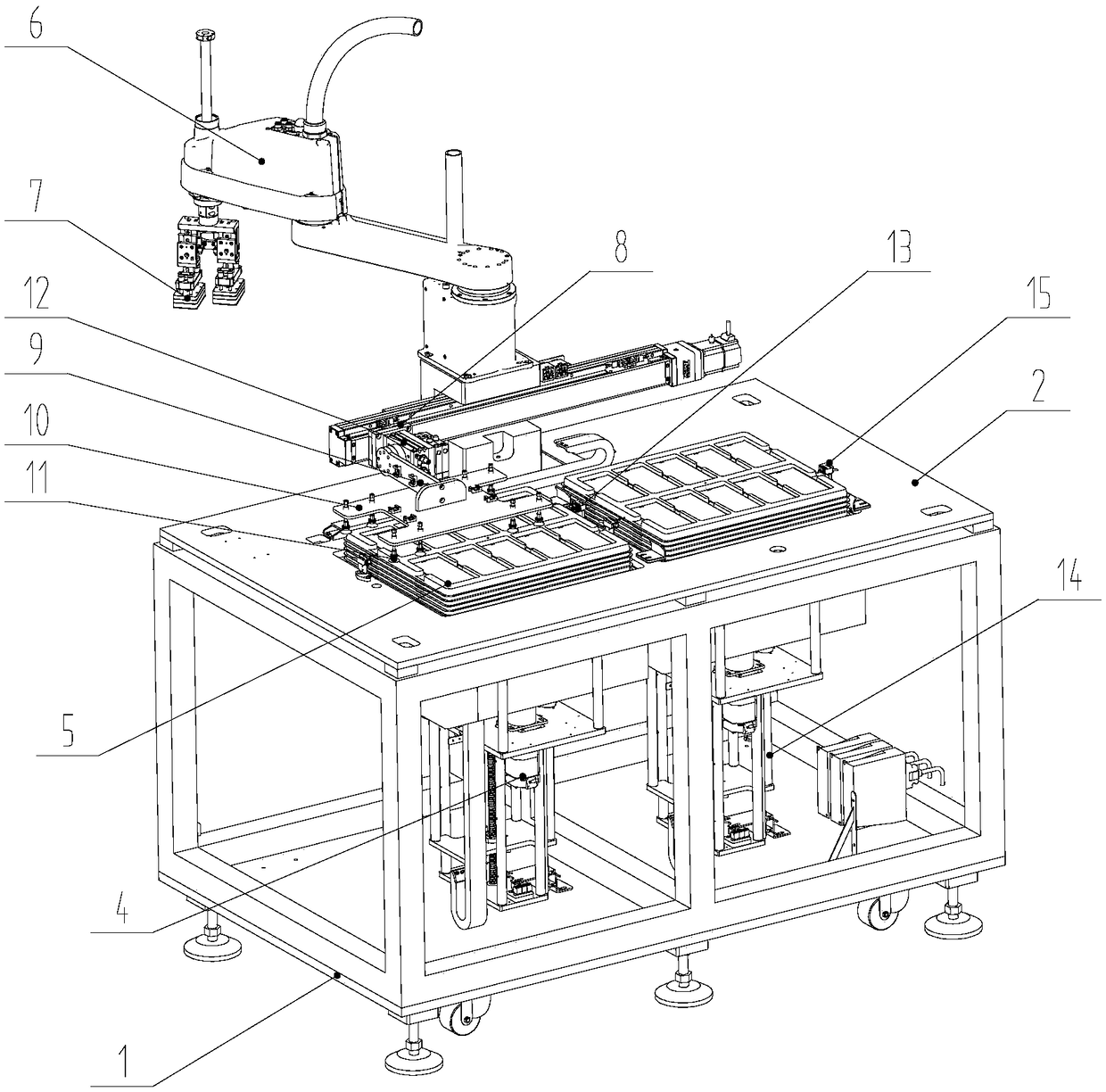
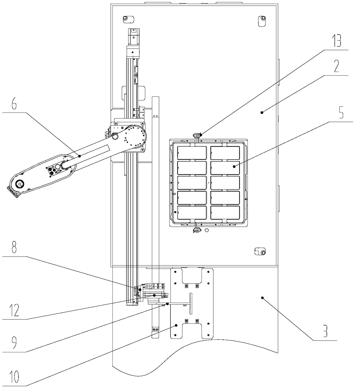
[0026] Such as Figure 1-2 As shown, a feeding device of an exposure machine includes a frame 1, a feeding platform 2 is arranged on the frame 1, a feeding station and a finished product storage station are arranged on the feeding platform 2, and the feeding station The filling station is provided with a feeding hole, and the feeding station is vertically slid to install a lifting table that can extend from the feeding hole. The lifting table is driven by the feeding lifting power device 4. A material tray 5 for placing mobile phone cases to be exposed; a manipulator 6 is installed on the feeding platform 2, and two first sucker assemblies 7 for absorbing the mobile phone case are installed on the terminal of the manipulator 6, and are installed on the workbench There is a transfer device for transferring the tray 5 to the finished product storage station.

[0027] In this embodiment, the transfer device includes a transfer slide 8 slidably installed between the feeding stati...

Embodiment 2

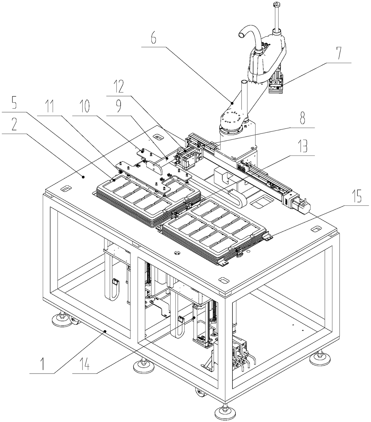
[0032] Such as image 3 As shown, a feeding device of an exposure machine includes a frame 1. A feeding platform 2 is arranged on the frame 1. A feeding station and a finished product storage station are arranged on the feeding platform 2. On the feeding station, There is a feeding hole, and the feeding station is vertically slid to install a lifting platform that can protrude from the feeding hole. The lifting platform is driven by the feeding lifting power device 4. There are multiple Place the material tray 5 of the mobile phone case to be exposed, a manipulator 6 is installed on the feeding platform 2, and two first sucker assemblies 7 for absorbing the mobile phone case are installed on the terminal of the manipulator 6, and are installed on the workbench for The transfer device that transfers the material tray 5 to the finished product storage station, the transfer device includes a transfer slide 8 that is slidably installed between the feeding station and the finished ...


PUM


Abstract

The invention discloses a feeding device of an exposure machine. The feeding device comprises a machine frame, a feeding platform is arranged on the machine frame, a supplement station and a finishedproduct storage station are arranged on the feeding platform, the supplement station is provided with a supplement passing hole, a lifting platform which can extend out of the supplement passing holeis vertically and slidably arranged at the supplement station, the lifting platform is driven by a supplement lifting power device, a plurality of trays used for placing to-be-exposed mobile phone shells are stacked on the lifting platform, a mechanical arm is arranged on the feeding platform, two first sucker assemblies used for sucking the mobile phone shells are arranged at the tail end of themechanical arm, and a working table is provided with a transferring device used for transferring the trays to the finished product storage station. The feeding device can realize automatic feeding ofthe mobile phone shells, the feeding efficiency is improved, and the labor cost is reduced.

Description

technical field [0001] The invention relates to a feeding device, in particular to a feeding device of an exposure machine. Background technique [0002] The current exposure machine for mobile phone cases includes an exposure main unit, on which a bottom plate is placed, and then the mobile phone case is manually placed on the bottom plate, and then exposed through the exposure main unit, because manual placement is prone to irregular situations, At this time, it is very difficult for the exposure machine to detect the edge of the mobile phone case, the calculation is complicated, and the manual operation is more complicated, which requires a lot of labor. Therefore, the current exposure machine is not reasonable for loading. Contents of the invention [0003] The technical problem to be solved by the present invention is to provide a feeding device for an exposure machine, which can realize automatic feeding of mobile phone shells, improve feeding efficiency, and reduce ...

Claims


Application Information

Patent Timeline
Patent Type & Authority Applications(China)
IPC IPC(8): B65G47/91B65G43/08G03F7/20
CPCB65G47/91B65G43/08B65G2203/042G03F7/20
Inventor 朱鹏飞潘钰吴景舟马迪
Owner JIANGSU GIS LASER TECH INC
Why Eureka
Try Eureka