
Hollow plate hinge joint structure with anchoring plates and construction method thereof

A technology for anchoring slabs and hollow slabs, used in bridge parts, erecting/assembling bridges, bridges, etc., can solve the problems of insufficient shear resistance of connecting steel bars, increased traffic safety hazards, and veneer stress, etc., to delay cracking and upward movement. Extension, reliable anchoring strength, effect of improving tensile capacity

Pending Publication Date: 2019-02-01
FUZHOU UNIVERSITY
View PDF0 Cites 2 Cited by
  • Summary
  • Abstract
  • Description
  • Claims
  • Application Information

AI Technical Summary

Problems solved by technology

However, due to the small size of the concrete structure at the hinged joints, post-casting, and the complex structure of the hinged joints, the construction quality of the hinged joints in the upper structure is the most difficult to guarantee
The existing hinged joint structure has insufficient shear resistance of the connecting steel bars, and the concrete construction quality at the hinged joint is poor, and damage occurs earlier, which eventually results in the stress of the veneer
The stress state of the veneer is very harmful to the bridge and has a wide range. In addition to causing damage to the beam itself, it can also cause damage to the bridge deck pavement, expansion devices, bridge supports, etc., reducing the flatness of the bridge deck, and even causing bridge failure. Phenomena such as bulging, breaking, and falling off of pavement affect driving comfort and increase driving safety hazards

Method used


Image

  • Hollow plate hinge joint structure with anchoring plates and construction method thereof
  • Hollow plate hinge joint structure with anchoring plates and construction method thereof
  • Hollow plate hinge joint structure with anchoring plates and construction method thereof

Examples


Embodiment Construction

[0035] In order to make the above-mentioned features and advantages of the present invention more comprehensible, the following specific embodiments are described in detail with reference to the accompanying drawings, but the present invention is not limited thereto.

[0036] refer to Figure 1 to Figure 8

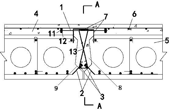
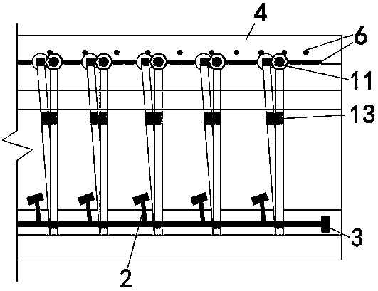
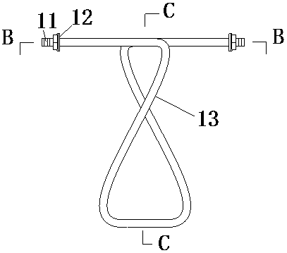
[0037] A hollow slab hinged joint structure with anchor plates, including hinged joints 8 arranged between adjacent hollow plates 5, connecting steel bars 1 with anchoring plates are arranged at longitudinal intervals in the hinged joints, and the connecting steel bars are spaced apart Set one for 150mm~200mm. The lower part of the hinged joint is longitudinally provided with two longitudinal steel bars 3 connected to the lower part of the connecting steel bar, and the two sides of the lower part of the hinged joint are longitudinally spaced with inclined steel bars 2 with anchor plates for connecting the hollow slab and the longitudinal steel bar. The top of the hollow ...


PUM


Abstract

The invention relates to a hollow plate hinge joint structure with anchoring plates and a construction method thereof. The hollow plate hinge joint structure with the anchoring plates comprises a hinge joint arranged between adjacent hollow plates; connecting reinforcements with the anchoring plates are arranged in the hinge joint in the longitudinal direction in a spaced manner; two longitudinalreinforcements connected with the lower parts of the connecting reinforcements are arranged at the lower part of the hinge joint in the longitudinal direction; inclined reinforcements with the anchoring plates, which are used for connecting the hollow plates with the longitudinal reinforcements, are correspondingly arranged on the two sides of the lower part of the hinge joint in the longitudinaldirection in a spaced manner; and a bridge deck pavement for filling the hinge joint is laid above the hollow plates. According to the hollow plate hinge joint structure with the anchoring plates, thestandard construction is made convenient, and the anti-shear and anti-bending ability of the connecting part of the hinge joint is greatly improved.

Description

technical field [0001] The invention relates to a hinged joint structure of a hollow plate with an anchor plate and a construction method thereof. Background technique [0002] The horizontal connection structure must be adopted between the hollow slab bridge plates to ensure that the plates bear the vehicle load together. However, due to the small size of the concrete structure at the hinged joints, post-casting, and the complex structure of the hinged joints, the construction quality of the hinged joints in the upper structure is the most difficult to guarantee. The existing hinged joint structure has insufficient shear resistance of the connecting steel bars, and the construction quality of the concrete at the hinged joint is poor, and damage occurs earlier, which eventually results in the stress of the veneer. The stress state of the veneer is very harmful to the bridge and has a wide range. In addition to causing damage to the beam itself, it can also cause damage to t...

Claims


Application Information

Patent Timeline
IPC IPC(8): E01D19/06E01D21/00
CPCE01D19/067E01D21/00
Inventor 王黎园唐朝阳陈永健郑雄英马思扬
Owner FUZHOU UNIVERSITY
Learn More