
Ceiling paint-brushing device for building construction

A technology for building construction and ceilings, which is applied in the direction of architecture and building construction, and can solve problems such as uneven pressure, less paint in the outer area, and low painting pressure

Inactive Publication Date: 2019-02-01
陈玉振
View PDF7 Cites 2 Cited by
  • Summary
  • Abstract
  • Description
  • Claims
  • Application Information

AI Technical Summary

Problems solved by technology

[0002] When painting the ceiling, conventional paint rollers cannot guarantee a low eccentricity tolerance, or if the cylinder is concave and uneven, then during the painting process, different parts of the paint receive different pressures, and it is easy to cause one end The pressure is high, while the painting pressure on other parts is very small, the paint lamination effect is poor, and the construction workers are also very laborious; if the conventional rubber column is used to adapt to the deformation, the problem of uneven pressure cannot be solved, and the rubber column itself also has errors, and When it is deformed, it will be greatly affected by mutual extrusion, forming protrusions or depressions
The ceiling part close to the fan-shaped protrusion or cylindrical protrusion will form an arc-shaped boundary area, that is, near the arc-shaped edge, or when painting the ring, fan-shaped end surface, etc., it is easy to cause brushing by using a conventional cylindrical roller. Uneven paint, for example, under the circular route, the outer area is larger than the inner area, which will easily cause less paint in the outer area; if the paint is not painted along the circular route, the route will overlap seriously, and repeated painting will easily cause excessive paint, and if there is Paint texture is not good

Method used


Image

  • Ceiling paint-brushing device for building construction
  • Ceiling paint-brushing device for building construction
  • Ceiling paint-brushing device for building construction

Examples


Embodiment Construction

[0027] The present invention will be further described in detail below in conjunction with the accompanying drawings and specific embodiments.

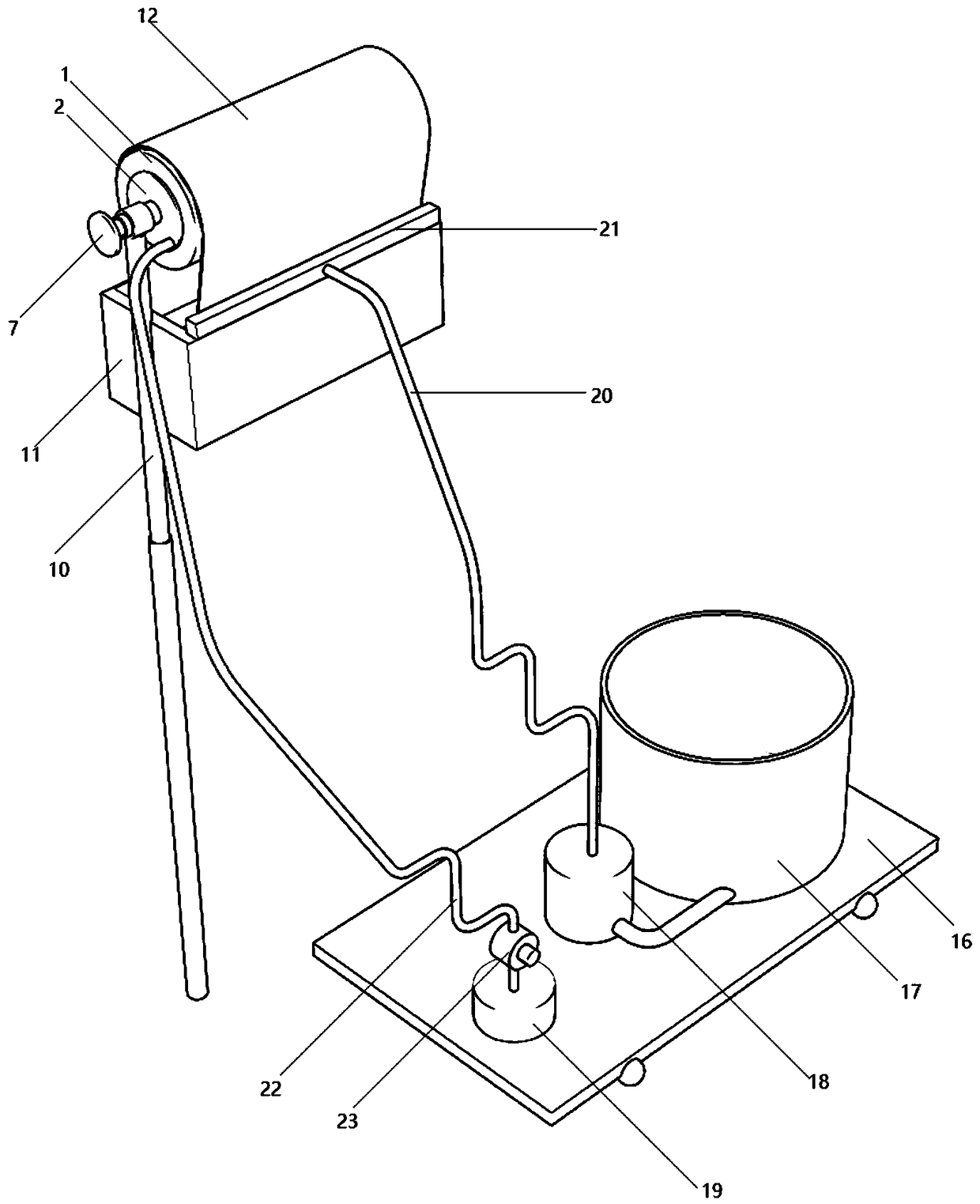
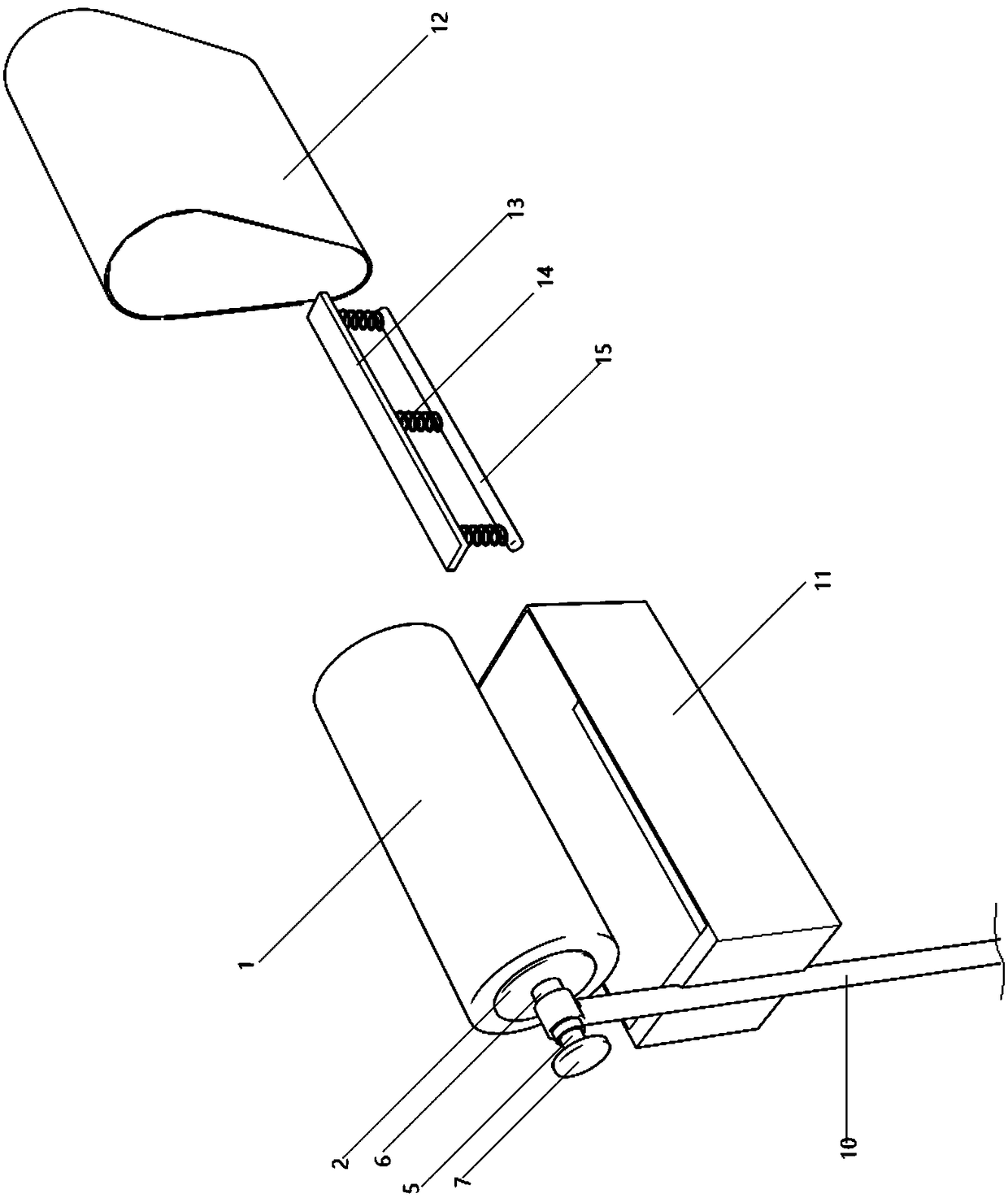
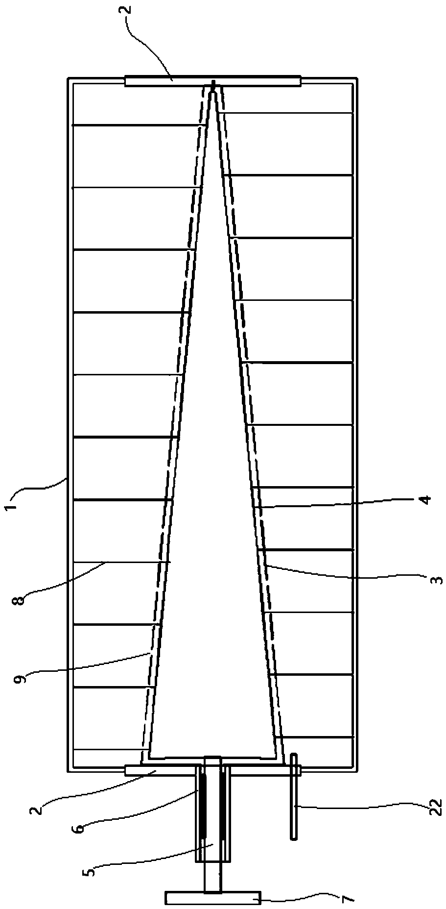
[0028] Such as Figure 1-7 As shown, a ceiling painting device for building construction includes a brushing unit and a feeding unit; the brushing unit includes a shaping rolling device and a brushing device; the shaping rolling device includes a cylindrical elastic bag 1 The left and right ends of the elastic bag 1 are sealed and embedded in the mounting plate 2; inside the elastic bag 1, a frustum-shaped limiting sleeve 3 is fixedly installed on the right end surface of the left mounting plate 2; the right end of the limiting sleeve 3 is connected to the The mounting plate 2 on the right side is fixedly connected; the truncated conical bobbin 4 is installed in rotation in the limiting casing 3; the right end of the bobbin 4 is rotationally connected with the right end of the limiting casing 3; The control shaft 5 is fixedly install...


PUM


Abstract

The invention discloses a ceiling paint-brushing device for building construction and relates to the technical field of building construction. The ceiling paint-brushing device comprises a brushing unit and a supplying unit. The brushing unit comprises a shape-fixing rolling device and a brushing device; the shape-fixing rolling device comprises a cylindrical elastic bag; a circular-truncated-cone-shaped wire reel is mounted in a limiting sleeve shell in a rotating fit mode; shape-fixing wires are evenly and fixedly connected to the inner wall of the elastic bag; the brushing device comprisesa collecting box and an annular brushing belt; and the supplying unit comprises a moving plate, and a paint barrel, a supplying pump and an inflation pump are mounted on the moving plate. The ceilingpaint-brushing device has the beneficial effects that the brushing unit can deform to adapt to even brushing of the plane, the near-arc-shaped edge, the arc-shaped end face and the like; and through inflation expansion of the elastic bag, each part, making contact with a ceiling, of the brushing belt can better bear force, and the paint is bonded with the ceiling more evenly and firmly.

Description

technical field [0001] The invention relates to the technical field of building construction. Background technique [0002] When painting the ceiling, conventional paint rollers cannot guarantee a low eccentricity tolerance, or if the cylinder is concave and uneven, then during the painting process, different parts of the paint receive different pressures, and it is easy to cause one end The pressure is high, while the painting pressure on other parts is very small, the paint lamination effect is poor, and the construction workers are also very laborious; if the conventional rubber column is used to adapt to the deformation, the problem of uneven pressure cannot be solved, and the rubber column itself also has errors, and When it deforms, it has a great influence on mutual extrusion, forming protrusions or depressions. The ceiling part close to the fan-shaped protrusion or cylindrical protrusion will form an arc-shaped boundary area, that is, near the arc-shaped edge, or wh...

Claims


Application Information

Patent Timeline
IPC IPC(8): E04F21/08
CPCE04F21/08
Inventor 陈玉振张亚伟李东军张帅李恒杰李战海
Owner 陈玉振
Learn More