
A conical radiation heating device

A radiant heating, conical technology, applied in the field of high temperature test, can solve the problems of internal pressure increase, cooling water vaporization, heating system difficult to install, etc., to achieve the effect of saving power loss, improving thermal efficiency, and uniform heat flow and temperature distribution

Active Publication Date: 2021-08-17
SHENYANG AIRCRAFT DESIGN INST AVIATION IND CORP OF CHINA
View PDF11 Cites 0 Cited by
  • Summary
  • Abstract
  • Description
  • Claims
  • Application Information

AI Technical Summary

Problems solved by technology

For the test piece with a conical structure, a cylindrical radiation heating system is often used to load the thermal load in the test. However, due to the structural characteristics of the cone, the distance between the cone tip of the test piece and the quartz lamp is relatively long, and the cylindrical radiation heating system The system will cause severe uneven heat flow or temperature distribution on the test piece, which will affect the reliability of the high temperature test
In addition, as the temperature required by the test increases, in order to improve the thermal efficiency, reflectors are often installed in the heating system to reflect the radiant heat, and in order to prevent the deformation of the reflector, the reflector is usually cooled in the form of hollow water cooling. However, due to the large area of ​​the reflector, the cooling water inside the reflector plus the weight of the reflector will bring serious additional mass, making it difficult to install the heating system, and excessive temperature may cause the cooling water inside the reflector to vaporize, and the internal Increased pressure and potential safety hazards

Method used


Image

  • A conical radiation heating device
  • A conical radiation heating device
  • A conical radiation heating device

Examples


Embodiment Construction

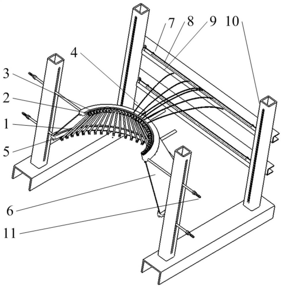
[0041] In order to make the purpose, technical solution and advantages of the application more clear, the technical solution in the embodiment of the application will be described in more detail below in conjunction with the drawings in the embodiment of the application. In the drawings, the same or similar reference numerals denote the same or similar elements or elements having the same or similar functions throughout. The described embodiments are some, but not all, embodiments of the application. The embodiments described below by referring to the figures are exemplary, and are intended to explain the present application, and should not be construed as limiting the present application. Based on the embodiments in this application, all other embodiments obtained by persons of ordinary skill in the art without creative efforts fall within the protection scope of this application. Embodiments of the present application will be described in detail below in conjunction with th...


PUM


Abstract

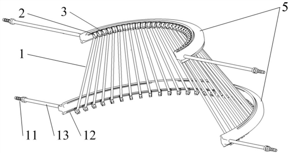
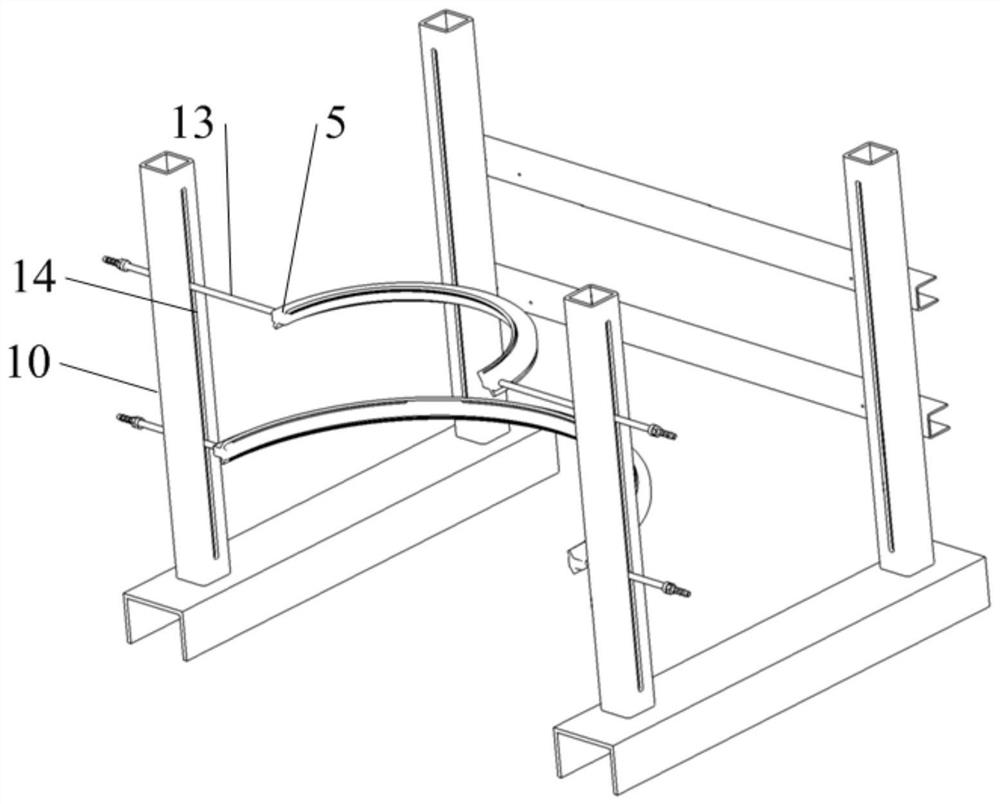
The application belongs to the field of high temperature testing, and particularly relates to a conical radiant heating device. The device includes: bracket, water cooling pipeline, heating element and reflector. The bracket is provided with a first installation groove; the water-cooling pipeline is arc-shaped, including two, the two water-cooling pipelines have different radii, and threaded rods are arranged at both ends of the water-cooling pipeline. It is installed in the first installation groove, and the two water cooling pipelines are provided with a second installation groove and a reflector installation hole; the heating element includes a plurality of heating elements, and the heating elements are installed in the second installation groove and are connected to Two of the water-cooling pipelines, wherein the heating element and the two water-cooling pipelines form a conical shape; the reflector is arranged on the outer side of the conical shape formed by the heating element and the two water-cooling pipelines, It is installed on the water cooling pipeline through the installation hole of the reflector plate. The present application makes the heat flow and temperature distribution on the surface of the test piece more uniform, improves the test efficiency and reduces the energy consumption.

Description

technical field [0001] The application belongs to the field of high temperature test, in particular to a conical radiation heating device. Background technique [0002] With the development of the aerospace industry, the flight speed of the aircraft is getting faster and faster, and the aircraft will be severely aerodynamically heated during the flight, which will reduce the structural strength and stiffness of the aircraft and affect the safety performance of the aircraft. Therefore, in the process of aircraft design and finalization, in order to study the performance of aircraft structures in high-temperature environments, various types of structural thermal tests need to be carried out, and radiant heaters are often used as the heating system for high-temperature tests in structural thermal tests. [0003] Common radiant heating systems in high temperature tests include flat-plate radiant heating systems and cylindrical radiant heating systems, which are simple in structu...

Claims


Application Information

Patent Timeline
Patent Type & Authority Patents(China)
IPC IPC(8): G01N17/00
CPCG01N17/00
Inventor 王鑫张雪飞顾亮亮张发明何乾强
Owner SHENYANG AIRCRAFT DESIGN INST AVIATION IND CORP OF CHINA
Learn More