Control method of cooking utensil

A technology for cooking utensils and control methods, which is applied to cooking utensil lids, cooking utensils, timing control ignition mechanisms, etc., can solve the problems of long overall cooking time, long waiting time for opening the lid, and inability to judge the normal operation of the air pump, etc. The effect of heating waiting time, shortening cooking time, and preventing overflow

Active Publication Date: 2019-02-05
ZHEJIANG SHAOXING SUPOR DOMESTIC ELECTRICAL APPLIANCE CO LTD
View PDF15 Cites 3 Cited by
  • Summary
  • Abstract
  • Description
  • Claims
  • Application Information

AI Technical Summary

Problems solved by technology

[0011] The main purpose of the present invention is to provide a control method for cooking utensils, so as to solve the problem in the prior art that the overall cooking time is too long, or the waiting time for opening the cover is too long, and solve the problem of the cooking utensils in the prior art before running. Unable to determine whether the air pump is working properly

Method used


Image

  • Control method of cooking utensil
  • Control method of cooking utensil
  • Control method of cooking utensil

Examples


Embodiment 1

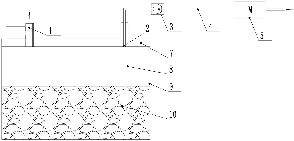
[0053] The cooking appliance of the first embodiment is an electric pressure cooker, figure 1 Shows the working schematic diagram of the electric pressure cooker for quick porridge cooking. The cooking appliance of the first embodiment includes an inner pot 9, a cooking cavity 8 is formed in the inner pot 9, and food materials 10 are contained in the cooking cavity 8. The electric pressure cooker also includes an exhaust port 1, a pressure limiting valve, an air intake port 2, a one-way valve 3, an air intake channel 4, an air pump 5, a pot cover 7 and a heating device. The air inlet 2 and the air outlet 1 are both arranged on the pot cover 7. The heating device is used for heating the cooking cavity. The aforementioned pressure limiting valve is also called an exhaust valve.

[0054] The air pump 5 is arranged on the air intake channel 4 to draw air outside the cooking appliance into the cooking cavity. The exhaust port 1 is provided with a pressure limiting valve, and the ex...

Embodiment 2

[0067] The working principle of the second embodiment is as follows:

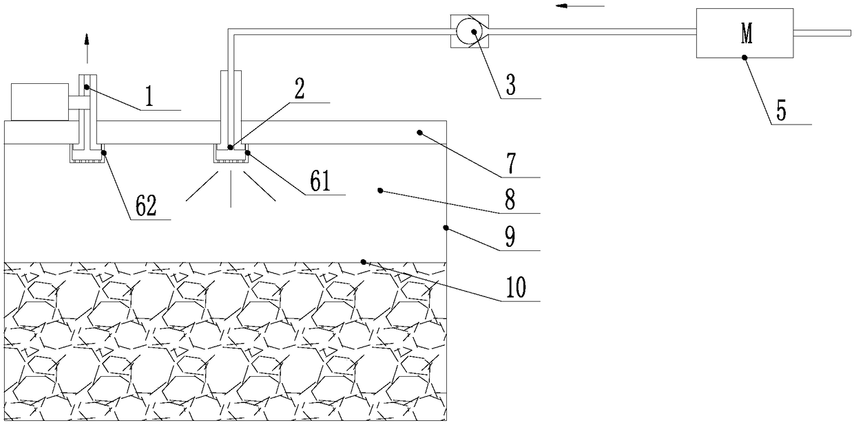
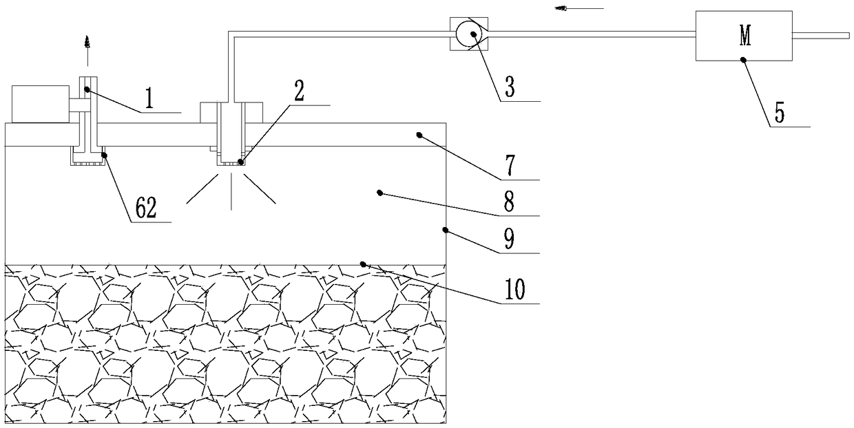
[0068] When the ingredients 10 are cooked in the closed cooking cavity 8 composed of the pot cover 7 and the inner pot 9, and the air pump 5 adds cold air to the closed cavity through the one-way valve 3, the air intake from the air inlet 2 passes through the air inlet cap 61 sprays the intake air to the surface of the food material 10 in the inner pot 9 so that the largest area has a cooling effect and reduces foam generation and overflow. At the same time, at the end of the discharge and the cooking process, the foam generated on the surface of the food material 10 cannot easily enter the air inlet 2 and the air outlet 1, thereby reducing the risk of overflow and facilitating cleaning.

[0069] Since the air intake cap 61 is provided at the air inlet as a guide part, the guide part disperses and / or changes the direction of the airflow at the air inlet, so the guide part can disperse the air intake above the fo...

Embodiment 4

[0074] The cooking appliance of the fourth embodiment is also an electric pressure cooker, which facilitates the frequent removal and cleaning of the inner lid of the lid 7. The one-way valve 3 is arranged at the communication point between the air intake passage 4 and the cooking cavity. The one-way valve 3 of the fourth embodiment is arranged at a separable position of the inner cover, which can be cleaned and prevents the food material in the inner cavity of the electric pressure cooker from entering the air inlet channel 4.

[0075] The electric pressure cooker of the fourth embodiment includes an inner pot 9, a cooking cavity 8 is formed in the inner pot 9, and food materials 10 are contained in the cooking cavity 8. The electric pressure cooker also includes an exhaust port 1, an intake port 2, a one-way valve 3, an intake passage 4, an air pump 5, an intake cap 61, an exhaust cap 62 and a pot cover 7. A pressure limiting valve is installed at the exhaust port 1.

[0076] W...


PUM


Abstract

The invention provides a control method of a cooking utensil. The cooking utensil comprises a pot body, a pot cover and an air pump, wherein the pot body is used for containing cooked food, the pot cover is arranged on the pot body, and the air pump can pump air into a cooking cavity of the pot body. The control method includes an air pump detection stage, wherein the air pump detection stage includes the steps that S11, the air pump operates for a first preset duration so as to pump air into the cooking cavity; S12, after the air pump operates for the first preset duration, if the cooking utensil receives a pressure rise signal, it is judged that the air pump works normally, and if the cooking utensil receives no pressure rise signal, it is judged that the air pump works abnormally. By means of the technical scheme, the problem that the overall cooking time is too long or the uncovering waiting time is too long in the prior art is solved, and the problem that whether or not an air pump works normally cannot be judged before a cooking utensil operates in the prior art is also solved.

Description

[0001] This application requires that the application date is July 28, 2017, the application number is 201710632451.0, and the invention title is "Cooking Appliances, Cooking Machines and Cooking Control Methods". The priority of the invention patent application and the application date are December 29, 2017. The application number is 201711498327.6, and the priority of the invention patent application with the title of "Cooking Appliance". Technical field [0002] The present invention relates to the field of small household appliances, and in particular to a method for controlling cooking appliances. Background technique [0003] When cooking utensils to cook porridge, porridge and other viscous foods, it is easy to produce foam and overflow. Therefore, during the cooking process, there is a long waiting period during the heating phase. Otherwise, once the pressure rises, there will be a risk of overflowing the pot. As a result, the cooking time is too long. [0004] In response ...

Claims


Application Information

Patent Timeline
Patent Type & Authority Applications(China)
IPC IPC(8): A47J27/08A47J36/00A47J36/38
CPCA47J27/00A47J27/004A47J27/08A47J27/0802A47J27/086A47J27/092A47J27/56A47J36/00A47J36/06A47J36/24A47J36/2483A47J36/32A47J36/38
Inventor 李桂荣凌金星刘日贵孟城城
Owner ZHEJIANG SHAOXING SUPOR DOMESTIC ELECTRICAL APPLIANCE CO LTD
Why Eureka
Try Eureka