Solid-liquid mixing equipment and method

A solid-liquid mixing and equipment technology, which is applied in the direction of mixing methods, liquid and solid mixing, mixers, etc., can solve the problems of low mixing efficiency, easy dead angle, uneven crushing, etc., achieve high mixing and crushing contact area, improve Particle fineness, the effect of prolonging the mixing time

Inactive Publication Date: 2019-02-05
哈尔滨万鑫石墨谷科技有限公司
View PDF5 Cites 0 Cited by
  • Summary
  • Abstract
  • Description
  • Claims
  • Application Information

AI Technical Summary

Problems solved by technology

However, these three methods all have certain limitations. First, there are easy dead angles in the mixing process, and there may eventually be some large particles or aggregates that affect subsequent processing, and when the viscosity is high, a considerable part of the material cannot be mixed. The second is that the mixing speed is slow, and when the viscosity of the material is relatively high, it is not easy to discharge the material; the third is that vacuum or large negative pressure is used, the energy consumption is high, and air intervention may occur
[0004] Therefore, there is a need for a solid-liquid mixing equipment and method to solve the problems of low mixing efficiency and uneven pulverization of existing equipment

Method used


Image

  • Solid-liquid mixing equipment and method
  • Solid-liquid mixing equipment and method

Examples


Embodiment 1

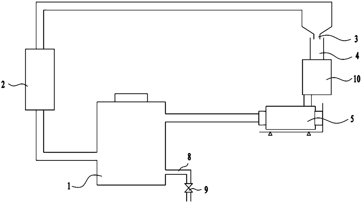
[0031] Such as figure 1 As shown, this embodiment provides a solid-liquid mixing device, which mainly includes a storage tank 1 , a first pump body 2 , a nozzle 3 , a material receiving pipe 4 , a second pump body 10 and a sand mill 5 . Wherein the storage tank 1, the first pump body 2, the nozzle 3, the material receiving pipe 4, the second pump body 10 and the sand mill can be regarded as being connected end to end in sequence. Specifically, the bottom of the storage tank 1 is connected to the feed port of the first pump body 2, and the discharge port of the first pump body 2 is connected to the tail of the nozzle 3. One end of the pipe 4 is located in the ejection direction of the feed liquid of the nozzle 3. In this embodiment, the opening of one end of the feed pipe 4 is located below the nozzle 3, and the other end of the feed pipe 4 is connected to the feed port of the second pump body 10. The outlet of the second pump body 10 is connected to the inlet of the sand mill...

Embodiment 2

[0035] For the sake of simplicity, only describe the difference between embodiment 2 and embodiment 1, and its difference is:

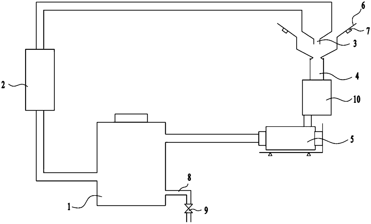
[0036] The solid-liquid mixing equipment in this embodiment also includes a discharge device 6 , which is funnel-shaped and connected to one end of the material receiving pipe 4 . The funnel-shaped feeding device 6 can increase the holding capacity of the material and prevent the material from leaking out. The discharging device 6 is used to add solid materials in batches, thereby increasing the quality of the materials in the storage tank 1 . After setting the feeding device 6, the quality of the feed liquid in the whole equipment can be increased without stopping the machine, thereby improving the mixing efficiency. An electromagnetic vibrator 7 is arranged on the top of the funnel-shaped feeding device 6 . The electromagnetic vibrator 7 can vibrate the side wall of the discharge device 6, so that the material can fall into the material receiving ...


PUM


Abstract

The invention discloses solid-liquid mixing equipment. The solid-liquid mixing equipment comprises a storage tank, a first pump body, a nozzle, a material receiving pipe, a second pump body, a sand mill,wherein a feed port of the first pump body is connected to the storage tank, the tail part of the nozzle is connected to a discharge port of the first pump body, one end of the material receiving pipe is located in the material liquid spraying direction of the nozzle, a feed port of the second pump body is connected to the other end of the material receiving pipe, a feed port of the sand mill is connected to a discharge port of the second pump body and is connected to the other end of the material receiving pipe, and a discharge port of the sand mill is connected to the storage tank. The invention further discloses a solid-liquid mixing method based on the solid-liquid mixing equipment. According to the solid-liquid mixing equipment, the storage tank is separated from the sand mill, a solid-liquid mixture can be uniformly treated, so that the mixing time of feed liquid is prolonged, and therefore the mixing degree is more uniform; and the nozzle is arranged, so that ejected fluid can enter the material receiving pipe quickly, so that negative pressure is formed at the periphery of a pipe orifice of the material receiving pipe, and the materials can be sucked into the material receiving pipe.

Description

technical field [0001] The invention relates to the technical field of dispersion mixing, in particular to a solid-liquid mixing device and method. Background technique [0002] In chemical production, it is often necessary to mix solids and liquids, so solid-liquid mixing equipment is required. Traditional solid-liquid mixing equipment generally includes a container, the upper end of the container has a feeding port, and a stirring device and / or a sand mill, etc. are arranged in the container, so that during the mixing process, solid and liquid phase substances are continuously injected from the feeding port, The solid is pulverized by a sand mill, and the solid and liquid are mixed together by a stirring device. However, for some high-viscosity liquids or powders that are prone to agglomeration, the solid-liquid is not easy to mix and requires certain grinding and crushing during the mixing process. In this case, because the solid material may always float on the liquid ...

Claims


Application Information

Patent Timeline
Patent Type & Authority Applications(China)
IPC IPC(8): B01F3/12B01F5/10
CPCB01F23/51B01F23/50B01F23/59B01F25/54B01F25/51B01F25/50B01F33/85B01F33/83612B01F35/7179
Inventor 杜新伟袁国辉杨斌黄须啟冯晓彤
Owner 哈尔滨万鑫石墨谷科技有限公司
Why Eureka
Try Eureka