Tilting type vertical taking-off and landing unmanned aerial vehicle

A technology for vertical take-off and landing and unmanned aerial vehicles, which is applied to vertical take-off and landing aircraft, unmanned aerial vehicles, rotorcraft, etc. UAV cruising time and other issues, to achieve the effect of saving power loss, avoiding inability to tilt, and reducing resistance

Inactive Publication Date: 2019-02-05
山东银赫智能科技股份有限公司
View PDF7 Cites 4 Cited by
  • Summary
  • Abstract
  • Description
  • Claims
  • Application Information

AI Technical Summary

Problems solved by technology

[0002] It is inconvenient for existing UAVs to take off and land, and generally take off and land by rolling (this method must require a certain length and width and a relatively flat ground as a runway for rolling, and it is generally difficult to find such a track in the outfield) ideal site); or take off and land with a parachute using a catapult device (this method requires a heavy catapult frame at all times, and the weight of a conventional UAV catapult frame is between 30-100KG, so it requires at least 2- Only 4 people can lift it, and if the flight site is on a mountain, it is very inconvenient to transport the catapult); or use rocket-assisted take-off and parachute landing (this method also requires a heavy rocket-assisted steel frame, generally At least 2-4 people are required to carry it, and the booster rocket is a one-time consumable and the cost is relatively high), while the existing vertical take-off and landing fixed-wing UAVs are all based on conventional fixed-wing UAVs. Or install 4 fixed electric motors on the tail boom, and then its working method is that the 4 additional motors are only responsible for the control of the take-off and landing of the aircraft, and these 4 motors do not participate in the control when the aircraft is cruising, and these 4 The two engines are generally vertically upward without aerodynamic rectification, which brings relatively large air resistance to the drone's cruise, thereby reducing the cruise time of the drone

Method used


Image

  • Tilting type vertical taking-off and landing unmanned aerial vehicle
  • Tilting type vertical taking-off and landing unmanned aerial vehicle

Examples


Embodiment Construction

[0012] In order to make the object, technical solution and advantages of the present invention clearer, the present invention will be further described in detail below in conjunction with the accompanying drawings and embodiments. It should be understood that the specific embodiments described here are only used to explain the present invention, not to limit the present invention.

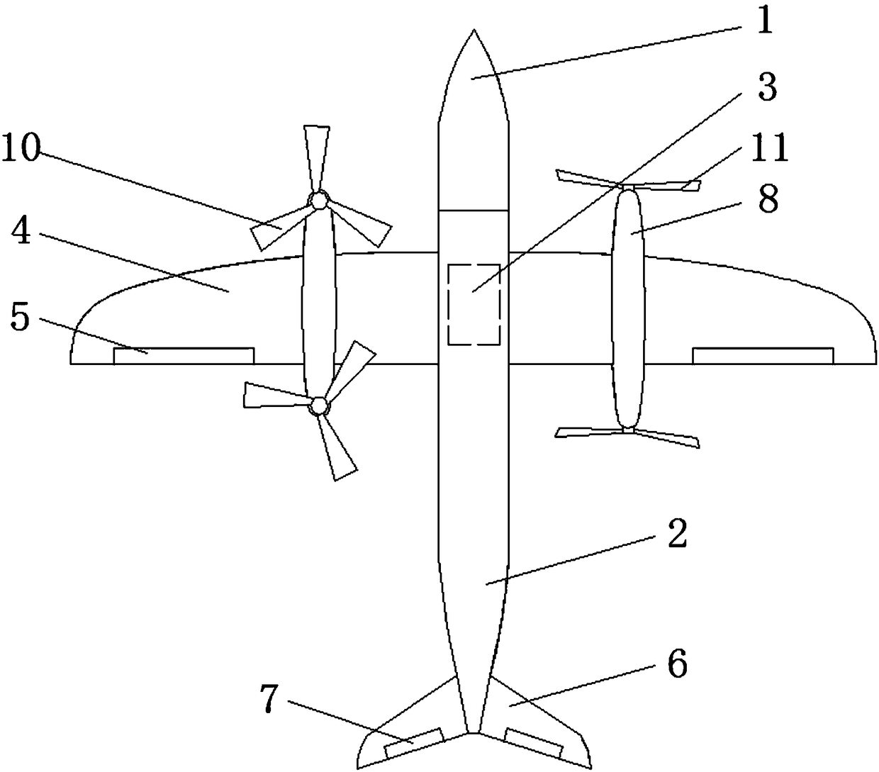
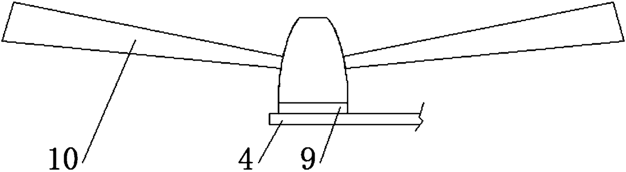
[0013] refer to Figure 1 to Figure 2 It can be seen that a tilting vertical take-off and landing unmanned aerial vehicle includes a mission cabin 1 and a fuselage 2, the mission cabin 1 and the fuselage 2 are integrally connected, and the fuselage 2 is provided with a flight control device near the mission cabin 1 The cabin 3 and the fuselage 2 are located on the left side and the right side of the flight control equipment cabin 3. Wings 4 are arranged. The two wings 4 are symmetrically arranged, and the wings 4 are provided with ailerons 5. The fuselage 2 The empennage 6 is provided at the tail ...


PUM


Abstract

The invention relates to unmanned aerial vehicles, in particular to a tilting type vertical taking-off and landing unmanned aerial vehicle. The tilting type vertical taking-off and landing unmanned aerial vehicle comprises a task warehouse and a vehicle body. The task warehouse is integrally connected with the vehicle body. A flight control equipment cabin is arranged at the position, close to thetask warehouse, of the vehicle body. Wings are arranged on the positions, located on the left and right sides of the flight control equipment cabin, of the vehicle body. The two wings are symmetrically arranged. Auxiliary wings are arranged on the wings. Tail wings are arranged on the tail part of the vehicle body. Steering rudders are arranged at the tail wings. The two steering rudders are symmetrically arranged. Fixing wings are arranged at the positions, close to the vehicle body, of the wings. The unmanned aerial vehicle requires no external assistance to take off and land, and thereforeelectric power loss is reduced when the unmanned aerial vehicle is in the air. Resistance due to engine failure to tilt is reduced. A screw propeller is folded backwards after tilting of the tiltingengine by folding propellers, and therefore resistance caused by a conventional non-folding propeller is greatly reduced.

Description

technical field [0001] The invention relates to an unmanned aerial vehicle, in particular to a tilting vertical take-off and landing unmanned aerial vehicle. Background technique [0002] It is inconvenient for existing UAVs to take off and land, and generally take off and land by rolling (this method must require a certain length and width and a relatively flat ground as a runway for rolling, and it is generally difficult to find such a track in the outfield) ideal site); or take off and land with a parachute using a catapult device (this method requires a heavy catapult frame at all times, and the weight of a conventional UAV catapult frame is between 30-100KG, so it requires at least 2- Only 4 people can lift it, and if the flight site is on a mountain, it is very inconvenient to transport the catapult); or use rocket-assisted take-off and parachute landing (this method also requires a heavy rocket-assisted steel frame, generally At least 2-4 people are required to carry...

Claims


Application Information

Patent Timeline
Patent Type & Authority Applications(China)
IPC IPC(8): B64C27/26B64C27/28B64C27/50B64C29/00
CPCB64C27/26B64C27/28B64C27/50B64C29/0033B64U10/25B64U2101/00B64U30/20B64U2101/30B64U50/13
Inventor 张虎王琦
Owner 山东银赫智能科技股份有限公司
Why Eureka
Try Eureka