Temperature control terminal and temperature control method

A terminal and control module technology, applied in the direction of machinery and equipment, can solve the problems that cannot be set separately, are not practical, etc.

Pending Publication Date: 2019-02-05
湖南同能机电科技有限公司
View PDF5 Cites 6 Cited by
  • Summary
  • Abstract
  • Description
  • Claims
  • Application Information

AI Technical Summary

Problems solved by technology

[0004] There are also temperature control terminals that can lock the temperature, but they cannot be set separately according to the cooling and heating modes. They can only set a maximum temperature limit and a minimum temperature limit. Since the temperature control logic of cooling and heating is just opposite, the administrator sets the cooling mode in summer. After that, the heating must be set again in winter, and it will be repeated in the second year, which is extremely impractical
[0005] There is also the patent CN200720067201.9 fan coil temperature limiting thermostat, which can also limit the minimum cooling temperature and the maximum heating temperature, but it must be realized through computer software programming, and the temperature control terminal must also have a communication interface. The button on the terminal realizes this function
In order to realize the networking temperature limiting function, hardware such as communication modules must be added to all temperature control terminals, computer equipment and control software must also be added, and construction wiring must be added. The investment cost will increase by 3-4 times, so at present Most of the temperature control terminals of central air conditioners do not have networking functions, so this technology is not practical

Method used


Image

  • Temperature control terminal and temperature control method

Examples


Embodiment 1

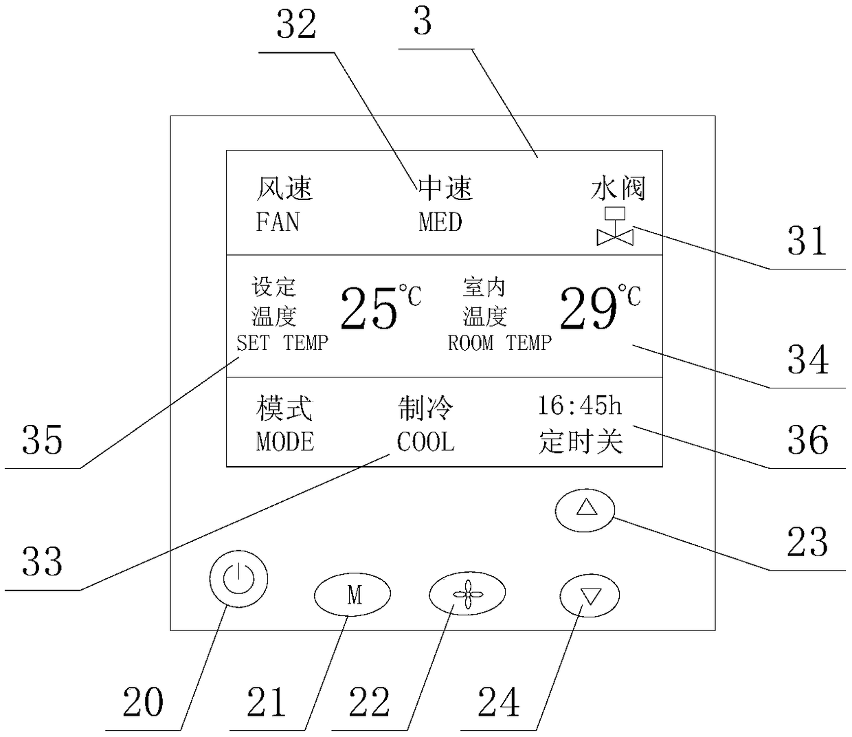
[0082] Embodiment 1: see as figure 1 , an electric valve self-cleaning device (or temperature control terminal), including a display screen, operation buttons and an output board, wherein the display screen can display operating mode 33 icons, including cooling, heating and air supply modes and wind speed icons 32, And the icons of indoor temperature 34, set temperature 35, date and time 36 and electric valve 31; The temperature control terminal can be in cooling, heating and air supply modes respectively by mode key 21.

[0083] The output module is electrically connected with the electric valve of the fan coil unit and the fan, and the electric valve includes its internal spool, and is connected with the fan coil unit through a water pipe; the electrical connection includes the direct connection of the output module with the electric valve and fan, and is directly driven by the output Electric valve and fan; it also includes the output module connected to the driving module...

Embodiment 2

[0107] The difference between embodiment 2 and embodiment 1 is that no temperature control terminal is used, the electric valve is directly electrically connected to the control center, and the electric valve is directly activated by the control center for self-cleaning.

Embodiment 3

[0108] The difference between Embodiment 3 and Embodiment 1 is that each switching action in the self-cleaning action of the electric valve adopts a positive and negative progressive type. When the control center or the control terminal drives the electric valve from closing to opening, the electric Valve opening signal, let the valve core move forward for a certain position, and then give the electric valve closing signal, the valve core moves reversely for a certain position, repeat several times, and then fully open the electric valve, and there can be a slight pause between the forward and reverse movements; And vice versa; this method is mainly suitable for electric valves with forward and reverse movement of the spool.


PUM


Abstract

The invention discloses a temperature control terminal and a temperature control method. The temperature control terminal comprises a control module, a display screen and an input module, wherein thedisplay screen and the input module are both connected to the control module; an output terminal for controlling a fan and a valve is arranged on the temperature control terminal; the input module isused for inputting an instruction or parameters; the input module is arranged to be capable of setting the mode, setting the target temperature and setting the temperature locking value, and the temperature locking value is the minimum locking refrigerating value or the maximum locking heating value; when the target temperature is set in a refrigerating mode and the control module detects that theset target temperature reaches the minimum locking refrigerating value, the control module does not respond to further reduce the set target temperature; and when the target temperature is set in a heating mode and the control module detects that the set target temperature reaches the maximum locking heating value, the control module does not respond to further set the target temperature. The temperature control terminal and the temperature control method are easily carried out, and the energy consumption can be obviously saved.

Description

technical field [0001] The invention belongs to the field of central air-conditioning terminal control, and relates to a temperature control terminal and a temperature control method. Background technique [0002] Fan coil unit is the terminal air-conditioning equipment of the central air-conditioning system. It is generally installed in the indoor ceiling and connected to the central air-conditioning system through pipes. The cold / hot water cools or heats the air through the coil, and then sends the air to the room through the fan; Usually, each fan coil unit is equipped with an electric valve, and the air conditioner is controlled by indoor users through a temperature control terminal. [0003] Existing temperature control terminal functions are aimed at users, pursuing excellent air-conditioning effects, without considering air-conditioning energy saving, so the temperature control setting range is generally fixed and cannot be adjusted, and existing temperature control t...

Claims


Application Information

Patent Timeline
Patent Type & Authority Applications(China)
IPC IPC(8): F24F11/64F24F11/52F24F11/46
CPCF24F11/46F24F11/52F24F11/64
Inventor 谢梦童献文
Owner 湖南同能机电科技有限公司
Why Eureka
Try Eureka