Device for measuring capacitance (C) and equivalent series resistance (ESR) in large frequency range

A frequency range and measurement device technology, applied in the field of capacitance C and ESR measurement devices in a large frequency range, can solve the problems of power supply and system operation failure, complex structure, expensive price, etc., and achieve a large measurement frequency range and simple circuit structure , the effect of accurate measurement

Inactive Publication Date: 2019-02-05
NANJING UNIV OF SCI & TECH
View PDF5 Cites 4 Cited by
  • Summary
  • Abstract
  • Description
  • Claims
  • Application Information

AI Technical Summary

Problems solved by technology

Generally speaking, after the circuit works for a period of time, the capacitance (Capacitance, C) and equivalent series resistance (Equivalent Series Resistance, ESR) of the capacitor will change. When the change is large, the capacitor will fail, and the capacitor will fail. Will cause power and system operation failure
Common LCR instruments are complex in structure and expensive, and cannot measure capacitance C and ESR in a large frequency range

Method used


Image

  • Device for measuring capacitance (C) and equivalent series resistance (ESR) in large frequency range
  • Device for measuring capacitance (C) and equivalent series resistance (ESR) in large frequency range
  • Device for measuring capacitance (C) and equivalent series resistance (ESR) in large frequency range

Examples


Embodiment Construction

[0013] The present invention will be described in further detail below in conjunction with the accompanying drawings and specific embodiments.

[0014] The invention designs a simple device for measuring the capacitance value C and the equivalent series resistance ESR in a large frequency range.

[0015] 1. Theoretical derivation:

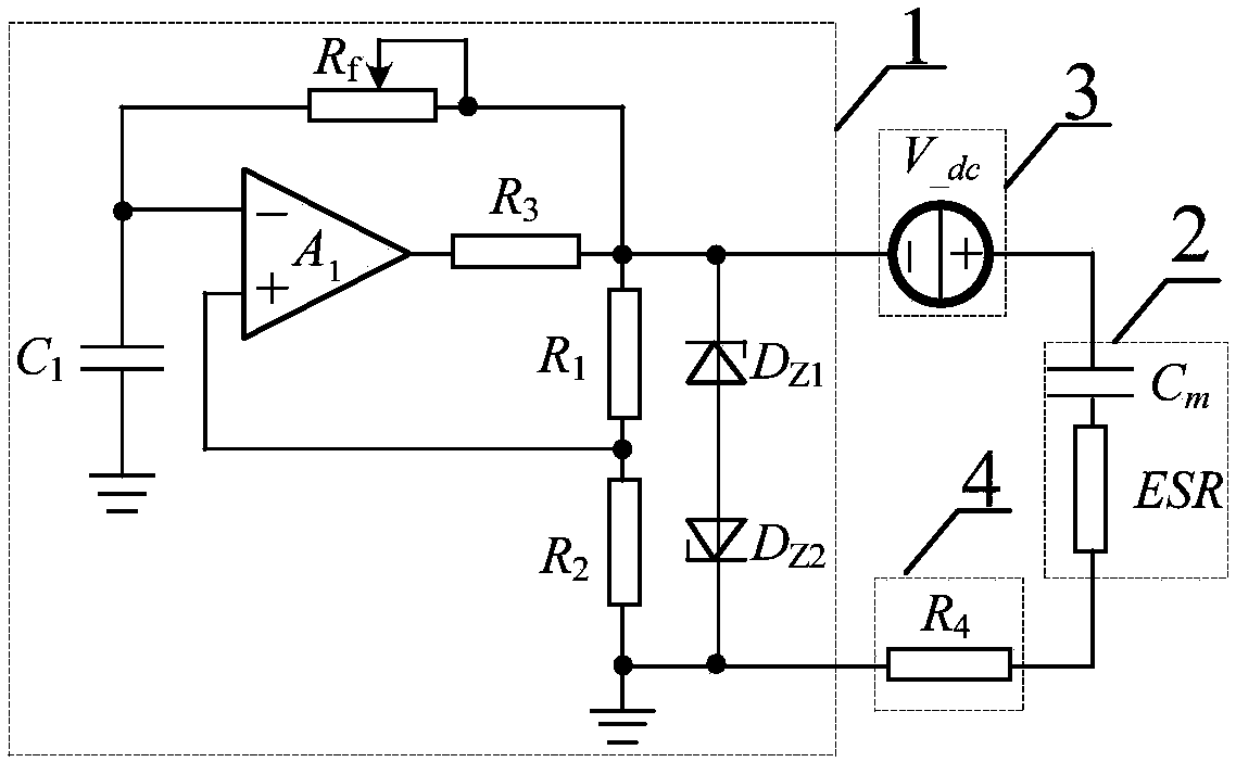
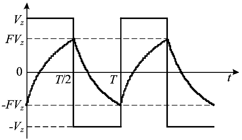
[0016] figure 1 is the circuit structure diagram of the capacitance measuring device, figure 2 is a typical period of a square wave, the output and capacitor C 1 voltage waveform on the When t=0, v c =-FV z , then in half a cycle, the capacitor C 1 voltage on v c Will be exponentially ruled by -FV z To +FV z The direction changes, and the capacitor terminal voltage changes with time as follows:

[0017]

[0018] Among them, v c1 is the capacitance C 1 The voltage across the terminal, V z is the voltage of the Zener diode, F is the positive feedback coefficient of the circuit, and

[0019] Let T be the period of the square wave, ...


PUM


Abstract

The invention discloses a device for measuring capacitance (C) and equivalent series resistance (ESR) in a large frequency range. The device for measuring the capacitance (C) and the ESR in the largefrequency range comprises a square wave generating circuit, a capacitor to be tested, a direct current voltage source and a power load resistor. One end of a first capacitor in the square wave generating circuit is connected with the negative input end of an operational amplifier, the other end of the first capacitor in the square wave generating circuit is a reference potential zero point, one end of a feedback resistor is connected with the negative input end of the operational amplifier, after the first resistor and a second resistor are connected in series, the common end is connected withthe positive input end of the operational amplifier, the other end of the first resistor is simultaneously connected with the feedback resistor and a third resistor, the second resistor is connectedwith the reference potential zero point, the other end of the third resistor is connected with the output end of the operational amplifier, after a first voltage stabilizing diode and a second voltagestabilizing diode are connected in series, one ends of the first voltage stabilizing diode and the second voltage stabilizing diode are connected with the common point of the first resistor and the third resistor, and the other ends of the first voltage stabilizing diode and the second voltage stabilizing diode are connected with the reference potential zero point. The device for measuring capacitance (C) and ESR in the large frequency range can accurately measure values of the capacitance (C) and the ESR, and has simple circuit structure, low cost and large measuring frequency range.

Description

technical field [0001] The invention belongs to the technical field of measurement in electric energy conversion devices, in particular to a measurement device for capacitance C and ESR in a large frequency range. Background technique [0002] Due to the needs of circuit design, capacitors are widely used in power electronic equipment. Generally speaking, after the circuit works for a period of time, the capacitance (Capacitance, C) and equivalent series resistance (Equivalent Series Resistance, ESR) of the capacitor will change. When the change is large, the capacitor will fail, and the capacitor will fail. It will cause power and system operation failure. Common LCR instruments are complicated in structure and expensive, and cannot realize the measurement of capacitance C and ESR in a large frequency range. Contents of the invention [0003] The object of the present invention is to provide a measuring device for capacitance C and ESR with simple circuit structure, low...

Claims


Application Information

Patent Timeline
Patent Type & Authority Applications(China)
IPC IPC(8): G01R27/26G01R27/02
CPCG01R27/02G01R27/2605
Inventor 冒春艳姚凯李垒唐焕奇陈恺立
Owner NANJING UNIV OF SCI & TECH
Why Eureka
Try Eureka