Electrode housing device for spot welding

一种收纳装置、电极的技术,应用在电极支撑装置、电极特征、不提供电极屏蔽的电极夹等方向,能够解决电极损耗等问题,达到减少工作故障、外观良好、优异设计性的效果

Active Publication Date: 2019-02-05
KYOKUTOH
View PDF5 Cites 1 Cited by
  • Summary
  • Abstract
  • Description
  • Claims
  • Application Information

AI Technical Summary

Problems solved by technology

Also, since the electrodes wear out due to repeated spot welding, they need to be replaced periodically

Method used


Image

  • Electrode housing device for spot welding
  • Electrode housing device for spot welding
  • Electrode housing device for spot welding

Examples


Embodiment Construction

[0040] Hereinafter, embodiments of the present invention will be described in detail with reference to the drawings. It should be noted that the following description of the preferred embodiments is exemplary only in nature.

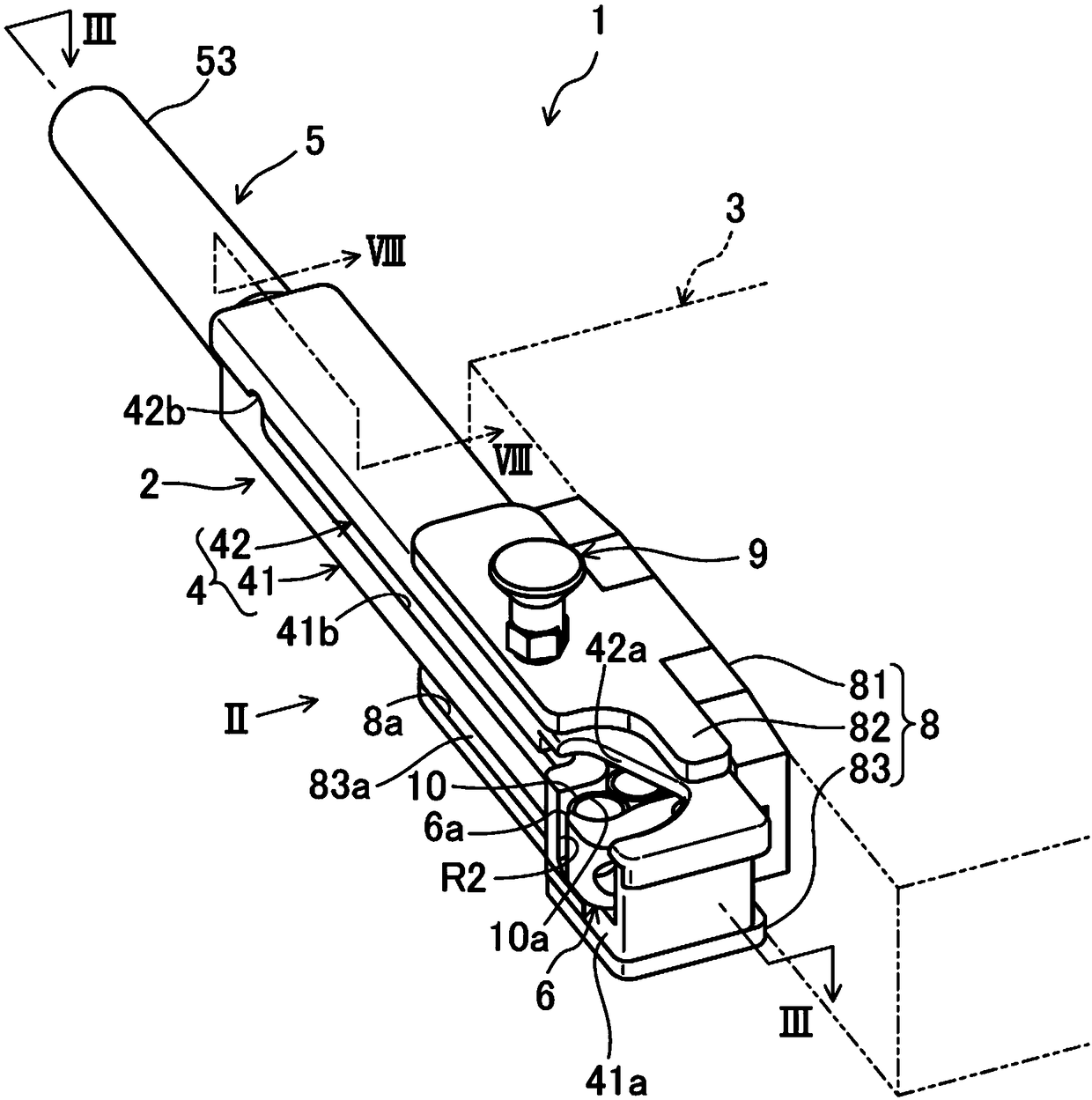
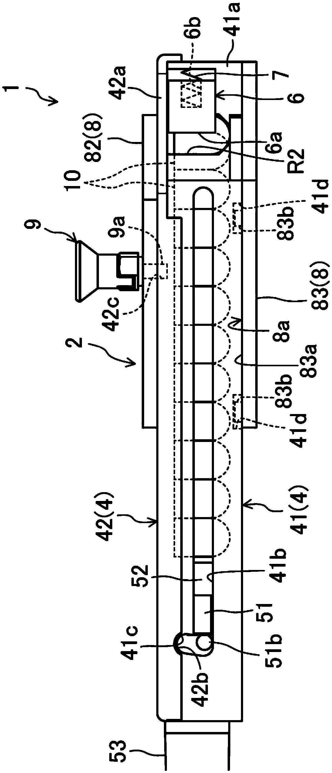
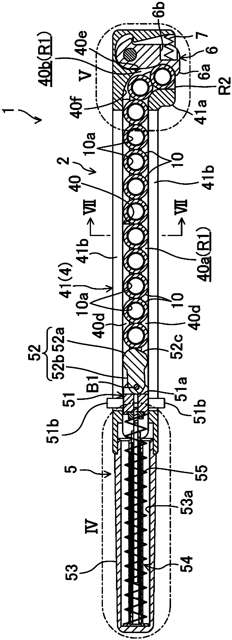
[0041] figure 1 and figure 2 The electrode storage device 1 for spot welding according to the embodiment of the present invention is shown. This electrode accommodating device 1 is arranged on the side of the vehicle body assembly passage in the automobile production line, so that the spot welding electrode 10 can be installed on the handle 11 of the welding torch held by the welding robot (refer to Figure 5 ) form accommodates a plurality of the electrodes 10.

[0042] The electrode storage device 1 includes a device main body 2 extending linearly, and the device main body 2 has a housing case 4 in an approximately rectangular cylindrical shape.

[0043] The receiving case 4 includes a U-shaped case body 41 with a U-shaped cross section on the bac...


PUM


Abstract

An accommodating case (4) has an accommodating passage (R1) that linearly accommodates a plurality of electrodes (10) in the interior thereof. An electrode outlet (R2) that communicates with the accommodating passage (R1) is formed in one end of the accommodating case (4). A pressing unit (5) presses the plurality of electrodes (10), which are in a state of being set in a row accommodated in the accommodating passage (R1), toward one end of the accommodating passage (R1). A lever member (6), by swinging, switches unloading of the electrodes (10) from the electrode outlet (R2) between a regulated state and an open state. A regulating coil spring (7) biases the lever member (6) so as to swing in one direction.

Description

technical field [0001] The present invention relates to an electrode storage device for spot welding which stores, for example, electrodes for spot welding used in automobile production lines in a state attachable to a shank of a welding torch. Background technique [0002] Conventionally, in automobile production lines, multiple press-formed parts are joined together by spot welding to assemble vehicle frames, usually with a welding torch mounted on the tip of an industrial robot arm. [0003] However, the electrode is attached to the handle of the welding gun by fitting the front end of the handle of the welding gun into the fitting recess of the electrode. Also, since the electrodes wear out due to repeated spot welding, they need to be replaced periodically. Therefore, in order to efficiently attach the electrode to the handle of the welding torch when replacing the electrode, an electrode storage device for spot welding as disclosed in Patent Document 1 is installed in...

Claims


Application Information

Patent Timeline
Patent Type & Authority Applications(China)
IPC IPC(8): B23K11/30B23K11/11
CPCB23K11/11B23K11/3072B23K9/1336B23K9/282
Inventor 中岛弘太郎
Owner KYOKUTOH
Why Eureka
Try Eureka