
Disc brake device

A disc brake and suction device technology, applied in the direction of the type of brake, the brake in the axial direction, the components of the brake, etc., can solve the problems of difficult cooling of the disc brake device, unavoidable enlargement of the device, and reduced braking performance. , achieve the effect of suppressing the scattering of wear powder to the surrounding, preventing the increase in size, and preventing the reduction of the braking performance

Inactive Publication Date: 2019-02-05
AKEBONO BRAKE IND CO LTD
View PDF9 Cites 0 Cited by
  • Summary
  • Abstract
  • Description
  • Claims
  • Application Information

AI Technical Summary

Problems solved by technology

However, in the case of using such a conventional structure, although it is effective in preventing the scattering of abrasive powder, since a large cover is required, the size of the device is unavoidable.
In addition, it is difficult to cool the disc brake device installed in the cover body, and there is a possibility that the braking performance may be lowered.
[0011] In addition, the above-mentioned problem of scattering of wear powder is not limited to the floating type disc brake device, and also occurs in the opposed piston type disc brake device.

Method used


Image

  • Disc brake device
  • Disc brake device
  • Disc brake device

Examples


Embodiment Construction

[0161] [the first example of embodiment]

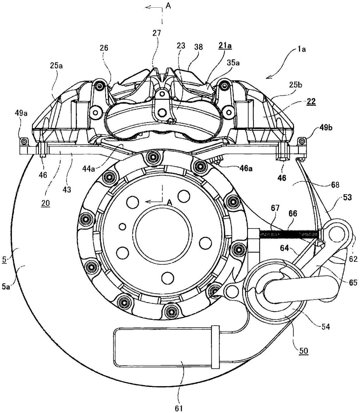
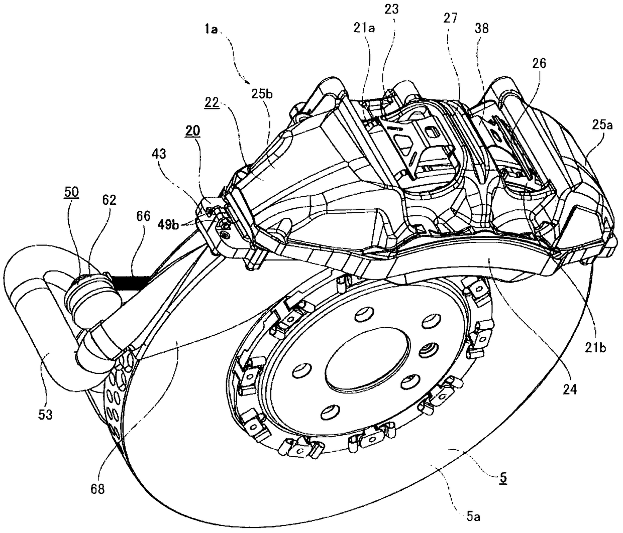
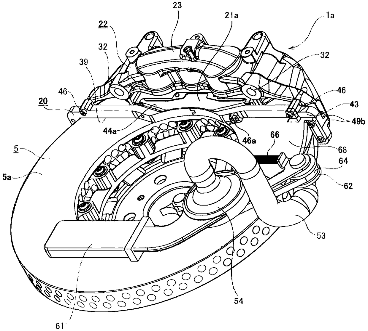
[0162] refer to Figure 1-10 A first example of an embodiment of the present invention will be described. In this first example, a case where an abrasion powder scattering preventing cover 20 is provided in an opposed-piston type disc brake device 1 a for preventing abrasion powder from scattering around the disc brake device 1 a will be described.

[0163] The disk brake device 1a of this first example is arranged axially ( figure 1 The inside and outside direction) clamped on both sides, so as to exert the braking force. In addition, the inner pad 21 a and the outer pad 21 b are axially movable supported by a caliper 22 provided so as to straddle a part of the circumferential direction of the rotor 5 from the radially outer side.

[0164] The caliper 22 is, for example, made of metal such as aluminum alloy, and has: an inner body portion 23 and an outer body portion 24 disposed on both inner and outer sides of the rotor 5; and t...


PUM


Abstract

On the inside of a caliper (22) configuring a disc brake device (1a), a hollow arcuate wear debris-scattering prevention cover (20) is set. A circumferential portion of a rotor (5) is disposed insidesaid wear debris-scattering prevention cover (20). During braking, by advancing an inner pad (21a) and an outer pad (21b) inward through pad insertion holes (44a) of the wear debris-scattering prevention cover (20), the sliding contact parts of the rotor (5) with said inner pad (21a) and outer pad (21b) are positioned inside the wear debris-scattering prevention cover (20). As a result, scatteringof wear debris into the surroundings is prevented.

Description

technical field [0001] The present invention relates to a disc brake device. Background technique [0002] As a brake device for braking an automobile, disk brake devices typified by floating type and opposed piston type are widely used because of excellent heat dissipation and ability to finely adjust power during running. Among them, the floating type disc brake device has the following structure: the caliper is supported so as to be able to move axially with respect to the support member, and in the caliper, a cylinder and a piston are provided only on one side of the rotor, and a pair of support members are provided. The pad is supported axially displaceably. In contrast, an opposed-piston disc brake device has a structure in which a pair of pads are axially movable relative to a caliper fixed to a vehicle body, A plurality of pistons are used to press the pads against the rotor. [0003] Figure 23-24 One example of the conventional configuration of the floating type...

Claims


Application Information

Patent Timeline
IPC IPC(8): F16D65/00F16D55/228
CPCF16D55/228F16D65/00F16D65/0031F16D2055/0029F16D2065/1396
Inventor 松田太郎野口哲弥
Owner AKEBONO BRAKE IND CO LTD
Learn More