Al technical title is built by PatSnap Al team. It summarizes the technical point description of the patent document.
A technology for forming molds and rear floors, applied in forming tools, manufacturing tools, metal processing, etc., can solve the problems of low machining accuracy of forming molds and complicated steps, and achieve the effect of preventing left and right deviation and ensuring accuracy
Inactive Publication Date: 2019-02-12
CHONGQING TONGDA MOLD CO LTD
View PDF10 Cites 0 Cited by
Summary
Abstract
Description
Claims
Application Information
AI Technical Summary
This helps you quickly interpret patents by identifying the three key elements:
Problems solved by technology
Method used
Benefits of technology
Problems solved by technology
[0005] The purpose of the present invention is to provide a rear floor longitudinal beam forming mold to solve the problems of low processing precision and cumbersome steps of the forming mold
Method used
Image
Click on the blue label to locate the original text in one second.
Reading with bidirectional positioning of images and text.
Examples
Embodiment Construction
[0019] Below in conjunction with accompanying drawing and embodiment the technical content of the present invention is further described:
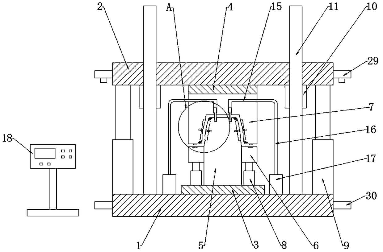
[0020] Figure 1~2 A rear floor stringer forming mold of the present invention is shown, comprising:
[0021] Lower mold base 1, upper mold base 2, lower backing plate 3, upper backing plate 4, lower punch 5, N lower movable mold 6, upper die 7, N hydraulic telescopic cylinders-8, P hydraulic telescopic cylinders 9. Q guide sleeves 10, Q guide posts 11, R punch holes 12, R punches 13, R hydraulic cylinders 14, R hydraulic inner tubes 15, R hydraulic outer tubes 16, R hydraulic pressure Pump 17, control box 18;
[0022] The lower backing plate 3 is arranged on the lower backing plate 1, the upper backing plate 4 is arranged on the upper backing plate 2, the lower punch 5 is arranged on the lower backing plate 3, and N hydraulic telescopic cylinders-8 are arranged on the lower backing plate 3, N lower movable molds 6 are connected to the ...
PUM
Abstract
The invention discloses a rear floor longitudinal beam forming mold which comprises a lower die holder, an upper die holder, a lower base plate, an upper base plate, a lower male die, N lower moving dies, an upper female die, N hydraulic telescopic cylinders I, P hydraulic telescopic cylinders II, Q guiding sleeves, Q guiding pillars, R punching holes, R punches, R hydraulic cylinders, R hydraulicinner pipes, R hydraulic outer pipes, R hydraulic pumps and a control cabinet. The lower base plate is arranged on the lower die holder; the upper base plate is arranged on the upper die holder; andthe lower male die is arranged on the lower base plate. According to the rear floor longitudinal beam forming mold provided by the invention, through arranging the lower male die, the N lower moving dies, the upper female die, the N hydraulic telescopic cylinders I and the P hydraulic telescopic cylinders II, the high-efficiency and high-quality forming of a rear floor longitudinal beam is realized, the production time is shortened, and the production cost is reduced.
Description
technical field [0001] The invention relates to a molding die, in particular to a rear floor stringer molding die. Background technique [0002] With the development of the economy and the improvement of people's living standards, the automobile has become one of the important means of transportation for people to travel, and the parts on the automobile are indispensable components of the automobile. The rear floor longitudinal beam on the car is one of the parts used in the car, and its quality directly affects the safety and stability of the car. At present, the rear floor longitudinal beam is mainly made of ultra-high-strength steel stamping. The cross-sectional structure of the rear floor longitudinal beam is designed as multiple bending surfaces to improve the rigidity of the rear floor longitudinal beam, thereby increasing the safety of the car. It is precisely because of the high strength and complex cross-sectional shape of the rear floor longitudinal beam that it i...
Claims
Application Information
Patent Timeline
Application Date:The date an application was filed.
Publication Date:The date a patent or application was officially published.
First Publication Date:The earliest publication date of a patent with the same application number.
Issue Date:Publication date of the patent grant document.
PCT Entry Date:The Entry date of PCT National Phase.
Estimated Expiry Date:The statutory expiry date of a patent right according to the Patent Law, and it is the longest term of protection that the patent right can achieve without the termination of the patent right due to other reasons(Term extension factor has been taken into account ).
Invalid Date:Actual expiry date is based on effective date or publication date of legal transaction data of invalid patent.