Hardware drilling device

A drilling device and hardware technology, applied in the field of hardware processing, can solve the problems affecting production efficiency, debris and dust splashing, time-consuming and labor-intensive, etc., to avoid debris and dust splashing, manual operation, and convenient operation.

Pending Publication Date: 2019-02-12
浙江亚普自动化装备科技股份有限公司
View PDF1 Cites 6 Cited by
  • Summary
  • Abstract
  • Description
  • Claims
  • Application Information

AI Technical Summary

Problems solved by technology

[0005] Aiming at the deficiencies of the prior art, the present invention provides a drilling device for hardware, which has the advantages of being easy to adjust the position of the drill, convenient to operate, effectively cooling down the drilling process, convenient for grinding the hardware, and has the advantages of a wide grinding range. It solves that the position of the drill bit of the current hardware drilling machine is not easy to adjust during the working process, and cannot fully adapt to the position and shape of various hardware parts. It is necessary to manually adjust the position of the drill bit of the hardware drilling machine, which affects production efficiency. At the same time, it is grinding The high temperature generated during the process and the splashing of debris and dust will bring safety hazards to the on-site production. At the same time, some hardware parts need to be ground again after drilling, and most drilling machines do not have grinding functions. Need to rework again, time-consuming and labor-intensive problems

Method used


Image

  • Hardware drilling device
  • Hardware drilling device

Examples


Embodiment Construction

[0022] The following will clearly and completely describe the technical solutions in the embodiments of the present invention with reference to the accompanying drawings in the embodiments of the present invention. Obviously, the described embodiments are only some, not all, embodiments of the present invention. Based on the embodiments of the present invention, all other embodiments obtained by persons of ordinary skill in the art without making creative efforts belong to the protection scope of the present invention.

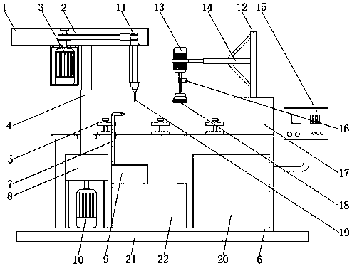
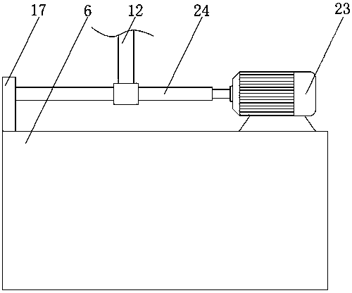
[0023] see Figure 1-2 , a drilling device for hardware, including a transmission box 1, a first motor 3 is fixedly installed on the bottom of the transmission box 1, the specific type of the first motor 3 is a three-phase asynchronous motor, and the specific model is Y2-90S-2, The output shaft of the first motor 3 runs through and extends to the inner top wall of the transmission box 1, the outer side of the output shaft of the first motor 3 is movably connec...


PUM


Abstract

The invention relates to the technical field of hardware machining, and discloses a hardware drilling device. The hardware drilling device comprises a transmission box, wherein a first motor is fixedly installed at the bottom of the transmission box, an output shaft of the first motor penetrates through and extends to the inner top wall of the transmission box, the outer side of the output shaft of the first motor is movably connected with a transmission belt wheel, and the other side of the transmission belt wheel is movably connected with a rotating shaft. According to the hardware drillingdevice, through the cooperation of a second motor and a reduction gear box, the first motor is enabled to work by controlling a control panel, after the first motor is started, the transmission belt wheel is driven to rotate, the transmission belt wheel drives a drill bit on the rotating shaft to rotate, meanwhile, the reduction gear box can reduce the rotating speed of an output shaft of the second motor, the drill bit can be conveniently adjusted to the required direction, drilling work is carried out by adjusting the height of a first hydraulic rod, manual operation by workers is avoided inthe using process, so that the purpose that the position of the drill bit is conveniently adjusted so as to realize convenient operation is achieved.

Description

technical field [0001] The invention relates to the technical field of hardware processing, in particular to a drilling device for hardware. Background technique [0002] Drilling machine is also known as drilling machine, punching machine, drilling machine and through-hole machine, etc., specifically refers to the use of tools that are harder and sharper than the target object through rotary cutting or rotary extrusion to leave holes on the hardware. Mechanical equipment for laying cylindrical holes or holes, with the development of the times and the improvement of the drilling technology of automatic drilling machines, the advantages of using automatic drilling machines to drill various hardware are obvious. [0003] Under the existing production environment, the position of the drill bit of the hardware drilling machine is not easy to adjust during the working process, and cannot fully adapt to the position and shape of various hardware parts. It is necessary to manually ...

Claims


Application Information

Patent Timeline
Patent Type & Authority Applications(China)
IPC IPC(8): B23P23/04
CPCB23P23/04
Inventor 陈伟
Owner 浙江亚普自动化装备科技股份有限公司
Why Eureka
Try Eureka