A Fast Focusing Method for Robot Vision Servo System
A robot vision and servo system technology, applied in the field of focusing, can solve the problems of poor zoom ability, difficulty in meeting the real-time requirements of visual servo, slow speed, etc., to achieve the effect of ensuring image clarity and shortening the duration of fast automatic focusing
- Summary
- Abstract
- Description
- Claims
- Application Information
AI Technical Summary
Problems solved by technology
Method used
Image
Examples
specific Embodiment approach 1
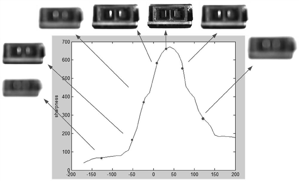
[0025] A fast focusing method of a robot visual servo system according to the present embodiment, the method is as follows: firstly, collecting the current of multiple groups of liquid cameras with maximum sharpness, and the distance data of the liquid camera from the target object; then, establishing the current and The relationship model between the distances, and the unknown parameters in the model are determined by system identification and parameter fitting methods, and the final relationship model is determined; finally, the distance data between the camera and the target object is obtained and substituted into the determined final relationship model, and inversely Push the current value required by the liquid lens to zoom, and then control the liquid lens to zoom in real time.
specific Embodiment approach 2
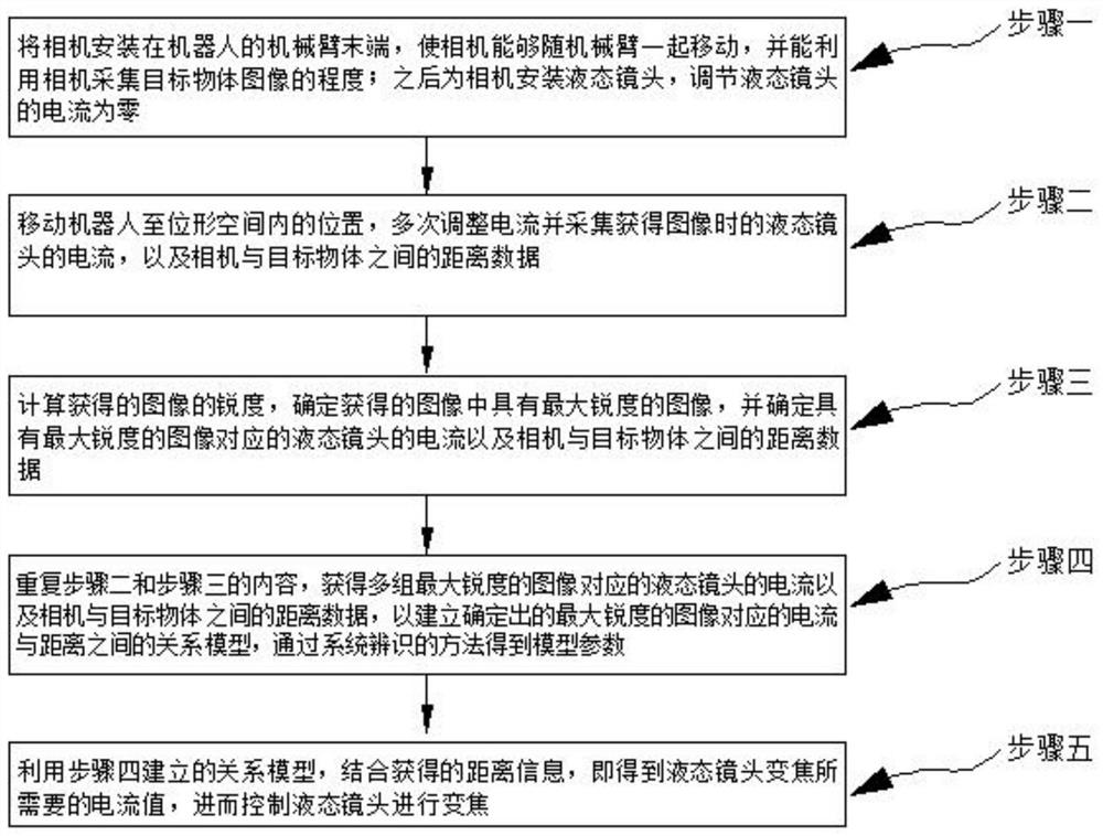
[0026] The difference from Embodiment 1 is that a fast focusing method of a robot visual servo system in this embodiment, such as figure 1 As shown in the flow chart, the method comprises the following steps:
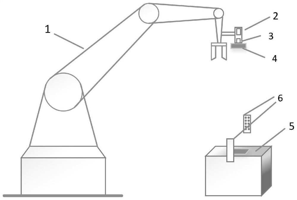
[0027] Step 1. Install the camera at the end of the robotic arm of the robot, so that the camera can move with the robotic arm, and the camera can be used to collect images of the target object; then install a liquid lens for the camera, and adjust the current of the liquid lens to zero;
[0028] Step 2. Move the robot to the position where the target object can be photographed in the configuration space, adjust the current multiple times and collect the current of the liquid lens when the image is obtained, as well as the distance data between the camera and the target object; in the configuration space, Refers to the position where the robot performs the normal shooting work of the target object;
[0029] Step 3, calculating the sharpness of the obtained image, deter...
specific Embodiment approach 3
[0032] The difference from the second specific embodiment is that in the fast focusing method of a robot visual servo system in this embodiment, in the second step, the robot is moved to a position where the target object can be photographed in the configuration space, the current is adjusted multiple times and The process of collecting the current of the liquid lens when the image is obtained, and the distance data between the camera and the target object is as follows:
[0033] Step 21. Move the robot to the configuration space of the manipulator, adjust the camera installed at the end of the manipulator to the position where the target object can be photographed, set the current of the liquid lens to zero, and adjust the camera so that the image in the camera field of view has a relatively high good clarity;
[0034] Step 22: Move the robotic arm, and calculate the vertical distance between the camera and the top surface of the target object according to the robot model; ad...
PUM
 Abstract
Description
Claims
Application Information
 - R&D
- Intellectual Property
- Life Sciences
- Materials
- Tech Scout
- Unparalleled Data Quality
- Higher Quality Content
- 60% Fewer Hallucinations
Browse by: Latest US Patents, China's latest patents, Technical Efficacy Thesaurus, Application Domain, Technology Topic, Popular Technical Reports.
© 2025 PatSnap. All rights reserved.Legal|Privacy policy|Modern Slavery Act Transparency Statement|Sitemap|About US| Contact US: help@patsnap.com


