Roller vacuum drying bin with cooling section

A technology of drum vacuum and drying warehouse, used in drying solid materials, non-progressive dryer, drying solid materials without heating, etc. Connection firmness, negative pressure resistance and anti-flattening, ensuring the effect of anti-flattening

Inactive Publication Date: 2019-02-12
程长春
View PDF0 Cites 1 Cited by
  • Summary
  • Abstract
  • Description
  • Claims
  • Application Information

AI Technical Summary

Problems solved by technology

[0002] Nowadays, in the processing and production fields of grain, food, chemical industry, medicine, agricultural by-products, pasture, etc., it is necessary to heat and dry the materials under vacuum conditions; the heat exchange of the drum drying chamber of the vacuum drying equipment on the market is mostly in the form of pipes. , Interlayer heating method for heat exchange and heat dissipation, but their radiators are large in size, small in heat dissipation area, and low in efficiency of heat energy use
Wet materials often form agglomerates in a vacuum state, resulting in uneven drying of wet materials and affecting the drying quality of materials
At present, the failure rate of the drum drying chamber on the market is high during use. The heat dissipation pipe in the drying chamber is worn by the material during the heat conduction and heat exchange process. " is scrapped and cannot be used

Method used


Image

  • Roller vacuum drying bin with cooling section
  • Roller vacuum drying bin with cooling section
  • Roller vacuum drying bin with cooling section

Examples


Embodiment 1

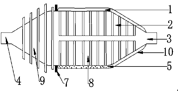
[0099] Such as figure 1 , figure 2 The shown drum vacuum drying chamber with a cooling section includes a heating chamber (1), a drying chamber (2), a heat-conducting working fluid (5), and a gear ring (7).

[0100] The exterior shape of the drum vacuum drying chamber with cooling section is cylindrical.

[0101] The heating chamber (1) is outside the drying chamber (2); the chamber body (10) at both ends of the heating chamber (1) and the chamber body (10) of the drying chamber (2) are fixedly connected as a whole.

[0102] The interior of the heating chamber (1) is sealed and airtight.

[0103] The appearance shape of the heating chamber (1) is cylindrical.

[0104] 1. The diameter of the heating chamber (1) is 1800mm.

[0105] 2. The length of the heating chamber (1) is 400mm.

[0106] When the length of the heating bin (1) exceeds 1500 mm, the bin body (10) of the heating bin (1) and the bin body (10) of the drying bin (2) are fixedly supported by brackets.

[0107]...

Embodiment 2

[0163] The combined structure of a drum vacuum drying chamber with a cooling section shown in Embodiment 2 is the same as that described in Embodiment 1, and the similarities will not be repeated.

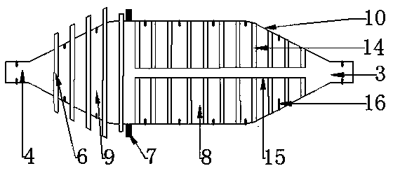
[0164] A drum vacuum drying chamber with a cooling section includes a heating chamber (1), a drying chamber (2), a heat-conducting working medium (5), and a gear ring (7).

[0165] The drying bin (2) includes a bin body (10), a cooling standpipe (6), a heat pipe (14), a spiral blade (16), and a fixing strip (15).

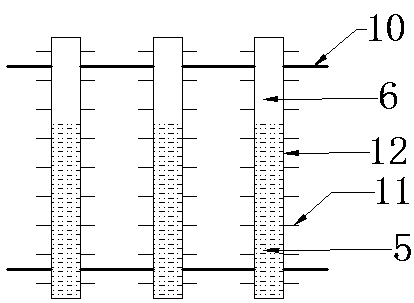
[0166] The heat dissipation riser (6) includes a metal tube (12) sealed at both ends, fins (11), and a heat-conducting working fluid (5).

[0167] Both ends of the heat dissipation standpipe (6) are fixed on the chamber body (10) inside the cooling section (9) of the drying chamber (2).

[0168] 1. Fix and weld the two ends of the cooling standpipe (6) to the chamber body (10) of the cooling section (9) of the drying chamber (2) by an electric welding machine.

[0169]...


PUM


Abstract

The invention provides a roller vacuum drying bin with a cooling section. The roller vacuum drying bin comprises a heating bin, a drying bin, heat conduction work media and a gear ring. An externallyarranged driving device drives the gear ring on the drying bin, and the gear ring can drive the drying bin to rotate. The heating bin is arranged on the outer surface of the drying bin. The drying bincomprises a bin body, a heat dissipation vertical pipe, heat pipes, screw blades and a fixing bar. The heat pipes are an independent whole overall welded to the part, in a drying section of the drying bin, of a bin body. The two ends of the heat dissipation vertical pipe are fixed to the parts, in a cooling section of the drying bin, of the bin body. The heat conduction work media in the heat pipes are heated by heat energy carried by the heat conduction work media in the heating bin to generate phase change gasification, the heat energy carried by the gasified heat conduction work media conducts heat conduction and heat exchange through heat pipe feed, the heat conduction and heat exchange speed of the heat energy is increased through the enlarged heat exchange area, the material dryingefficiency is improved, and the purpose of fast material drying is achieved. During material drying, the screw blades have stirring and pushing functions, materials are not likely to be agglomerated when being dried in the drying bin, and the dried materials are cooled in the cooling section of the drying bin.

Description

technical field [0001] The invention relates to a drum drying bin, in particular to a drum vacuum drying bin with a cooling section. Background technique [0002] Nowadays, in the processing and production fields of grain, food, chemical industry, medicine, agricultural by-products, pasture, etc., it is necessary to heat and dry the materials under vacuum conditions; the heat exchange of the drum drying chamber of the vacuum drying equipment on the market is mostly in the form of pipes. , Interlayer heating method for heat exchange and heat dissipation, but their radiators are large in size, small in heat dissipation area, and low in efficiency of heat energy use. Wet materials often form agglomerates under vacuum, which causes uneven drying of wet materials and affects the drying quality of materials. At present, the failure rate of the drum drying chamber on the market is high during use. The heat dissipation pipe in the drying chamber is worn by the material during the h...

Claims


Application Information

Patent Timeline
Patent Type & Authority Applications(China)
IPC IPC(8): F26B5/04F26B11/04F26B23/10F26B25/04F26B25/00
CPCF26B5/04F26B11/0445F26B23/10F26B25/00F26B25/04
Inventor 程长春
Owner 程长春
Why Eureka
Try Eureka