Culminated turboshaft engine, turboshaft engine culvert control system and control method

A turboshaft engine and control system technology, applied in the field of aero-engines, can solve the problem of low utilization rate of the bypass air flow of the particle separator, achieve the effects of improving the outlet flow field distribution, getting rid of enemy aircraft tracking, and improving work performance

Active Publication Date: 2020-04-21
AECC HUNAN AVIATION POWERPLANT RES INST
View PDF5 Cites 0 Cited by
  • Summary
  • Abstract
  • Description
  • Claims
  • Application Information

AI Technical Summary

Problems solved by technology

[0005] The invention provides a ducted turboshaft engine, turboshaft engine duct control system and control method to solve the technical problem of low utilization rate of the bypass air flow of the existing particle separator

Method used


Image

  • Culminated turboshaft engine, turboshaft engine culvert control system and control method
  • Culminated turboshaft engine, turboshaft engine culvert control system and control method
  • Culminated turboshaft engine, turboshaft engine culvert control system and control method

Examples


no. 2 example

[0069] The second embodiment of the turboshaft engine bypass control method of the present invention: the control method includes the following steps:

[0070] Collect the temperature of the power cabin, the weapon launch signal and the operating environment of the helicopter;

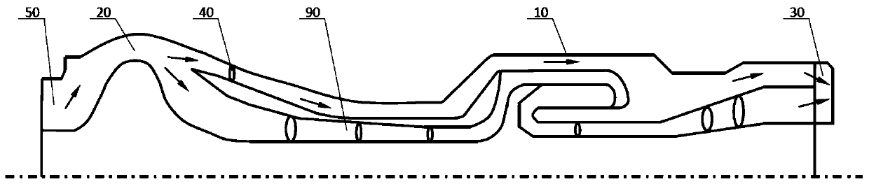
[0071] When the weapon launch signal is collected, the bypass air flow of the particle separator 20 is opened, the adjustment mechanism 40 is controlled, the flow channel area of ​​the entrance of the outer duct 10 is increased, and the air flow entering the outer duct 10 is increased.

[0072] In this embodiment, according to the received weapon launch signal, the synchronous control adjustment mechanism 40 increases the air flow rate entering the outer duct 10 to minimize the infrared radiation of the engine tail nozzle 30 .

no. 3 example

[0073] The third embodiment of the turboshaft engine bypass control method of the present invention: the control method includes the following steps:

[0074] Collect the temperature of the power cabin, the weapon launch signal and the operating environment of the helicopter;

[0075] Determine whether there are sand and dust particles in the operating environment of the helicopter. When there are sand and dust particles in the collection operation environment, open the bypass air flow of the particle separator 20; when the collection operation environment has no sand and dust particles, close the bypass of the particle separator 20 airflow.

no. 4 example

[0076] The fourth embodiment of the turboshaft engine bypass control method of the present invention: the control method includes the following steps:

[0077] Collect the temperature of the power cabin, the weapon launch signal and the operating environment of the helicopter;

[0078] When the helicopter is running in an environment with sand and dust, open the bypass air flow of the particle separator 20 to judge whether the temperature of the power cabin is greater than the preset value. The flow channel area increases the air flow entering the outer duct 10;

[0079] When the helicopter is running in an environment without sand and dust, close the bypass air flow of the particle separator 20; judge whether the temperature of the power cabin reaches a preset value, and when greater than the preset value, open the bypass air flow of the particle separator 20 to control The adjustment mechanism 40 expands the flow channel area of ​​the outer duct 10 to increase the air flow ...


PUM


Abstract

The invention discloses a culvert type turboshaft engine and a turboshaft engine culvert control system and method. According to the culvert type turboshaft engine, an outer culvert is arranged at theperiphery of a core engine and connected with a bypass flow channel of a particle separator, and thus bypass airflow of the particle separator enters the outer culvert and is utilized to cool a powercompartment and an outer culvert cartridge receiver; according to the turboshaft engine culvert control system, by collecting the temperature of the power compartment, an adjusting mechanism is controlled to adjust the air flow quantity entering the outer culvert and the core engine, thus the temperature of the power compartment is automatically adjusted, the working performance of the engine isimproved, and the working reliability of the engine and accessories is improved; and according to the turboshaft engine culvert control method, the operating environment of a helicopter, the temperature of the power compartment and a weapon launch signal generated by a weapon launch system are synthesized to control the bypass airflow of the particle separator, and thus the functions such as active particle separation, the adjustable temperature of the power compartment and jet nozzle infrared suppression are achieved.

Description

technical field [0001] The invention relates to the field of aeroengines, in particular to a ducted turboshaft engine. In addition, the present invention also relates to a duct control system and control method of a turboshaft engine. Background technique [0002] Helicopters need to fly in sandy and dusty environments near the ground. As the main power unit of helicopters, turboshaft engines generally have intake particle separators to ensure that turboshaft engines can work reliably in sandy and dusty environments. The current international advanced turboshaft The engines all use integral particle separators. The bypass air flow used to remove sand and dust at the engine inlet in the particle separator accounts for 15% to 20% of the total air flow at the engine inlet. The bypass air flow cannot be adjusted and is directly discharged outside the machine. [0003] Sand and dust generally only exist in the near-ground environment, and the proportion of helicopters working ne...

Claims


Application Information

Patent Timeline
Patent Type & Authority Patents(China)
IPC IPC(8): G05B19/04B01D45/16
CPCB01D45/16G05B19/04
Inventor 唐平一
Owner AECC HUNAN AVIATION POWERPLANT RES INST
Why Eureka
Try Eureka