
Boundary defect detection method and device and detection device

A technology of boundary defects and detection methods, applied in image data processing, instruments, calculations, etc., can solve the problems of low accuracy of detection methods, achieve high accuracy, improve robustness, and improve accuracy

Active Publication Date: 2019-02-12
苏州优纳科技有限公司
View PDF15 Cites 15 Cited by
  • Summary
  • Abstract
  • Description
  • Claims
  • Application Information

AI Technical Summary

Problems solved by technology

[0006] In view of this, the embodiment of the present invention provides a detection method, device and detection equipment for boundary defects to solve the problem of low accuracy of existing defect detection methods

Method used


Image

  • Boundary defect detection method and device and detection device
  • Boundary defect detection method and device and detection device
  • Boundary defect detection method and device and detection device

Examples


Embodiment Construction

[0073] In order to make the purpose, technical solutions and advantages of the embodiments of the present invention clearer, the technical solutions in the embodiments of the present invention will be clearly and completely described below in conjunction with the drawings in the embodiments of the present invention. Obviously, the described embodiments It is a part of embodiments of the present invention, but not all embodiments. Based on the embodiments of the present invention, all other embodiments obtained by those skilled in the art without creative efforts fall within the protection scope of the present invention.

[0074] According to an embodiment of the present invention, an embodiment of a detection method for boundary defects is provided. It should be noted that the steps shown in the flow charts of the accompanying drawings can be executed in a computer system such as a set of computer-executable instructions, and, Although a logical order is shown in the flowchart...


PUM


Abstract

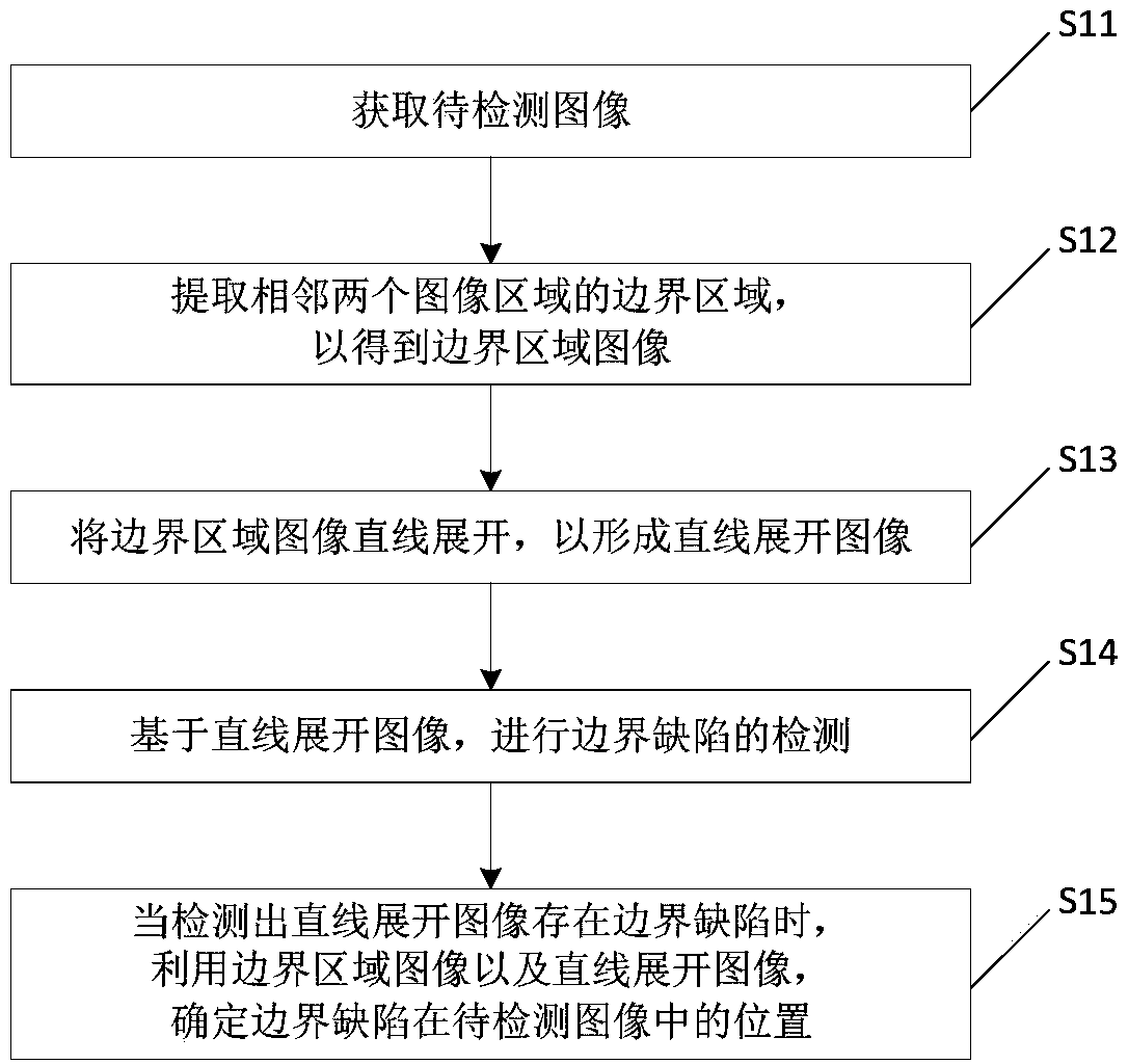
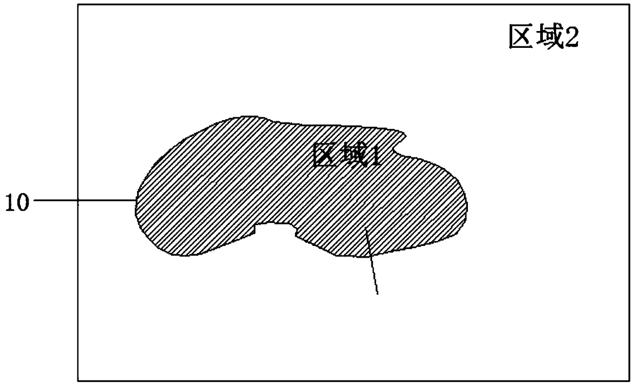
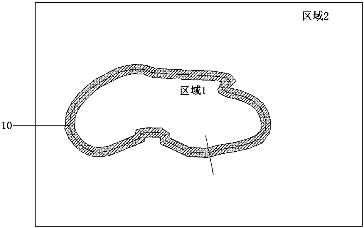
The invention provides a boundary defect detection method and device and a detection device, wherein the method comprises the steps of obtaining an image to be detected; extracting the boundary regions of two adjacent image regions to obtain boundary region images; linearly expanding the boundary region image to form a linearly expanded image; detecting the boundary defects based on the straight-line image; when the boundary defects are detected in the straight line image, determining the position of the boundary defects in the image to be detected by using the boundary region image and the straight line image. By extending a first preset distance and a second preset distance respectively to two adjacent image regions in the normal direction of each pixel point on the boundary line, the first boundary connection line and the second boundary connection line are obtained, namely, all the boundary defects of the image to be detected are divided into boundary regions by setting appropriateboundary detection ranges, and the defects crossing the boundary regions can be completely detected after the boundary regions are straightly expanded, thereby improving the detection accuracy.

Description

technical field [0001] The invention relates to the field of defect detection, in particular to a detection method, device and detection equipment for boundary defects. Background technique [0002] Since the surface defects of industrial products will have a negative impact on the aesthetics, comfort and performance of the product, the manufacturer will detect the surface defects of the product before the product leaves the factory, so as to find and control it in time. Among them, the most common surface defect is the boundary defect, and the boundary defect is divided into scratches, chipping, foreign matter, dirt, etc. according to the type of defect. [0003] Traditional defect detection mostly relies on manual detection, which is not only inefficient, but also causes false detection or missed detection due to human eye fatigue or subjective reasons. Therefore, with the rapid development of digital image technology, defect detection methods based on machine vision have...

Claims


Application Information

Patent Timeline
Patent Type & Authority Applications(China)
IPC IPC(8): G06T5/10G06T7/00G06T7/13G06T7/62G06T7/70
CPCG06T5/10G06T7/0002G06T7/13G06T7/62G06T7/70
Inventor 唐志峰王永超郑众喜李鹏杰
Owner 苏州优纳科技有限公司
Learn More