
Output signal control circuit and method

A technology for outputting signals and controlling circuits, used in instruments, static indicators, etc.

Active Publication Date: 2019-02-12
TCL CHINA STAR OPTOELECTRONICS TECH CO LTD
View PDF7 Cites 0 Cited by
  • Summary
  • Abstract
  • Description
  • Claims
  • Application Information

AI Technical Summary

Problems solved by technology

[0005] Therefore, the adjustable rising time and falling time of the output signal of the existing level shifter needs to be improved and developed.

Method used


Image

  • Output signal control circuit and method
  • Output signal control circuit and method

Examples


Embodiment Construction

[0013] Embodiments of the present invention are described in detail below, examples of which are shown in the drawings, wherein the same or similar reference numerals denote the same or similar elements or elements having the same or similar functions throughout. The embodiments described below by referring to the figures are exemplary only for explaining the present invention and should not be construed as limiting the present invention. Furthermore, the present disclosure repeats reference numerals and / or reference letters in different examples, such repetition is for the purpose of simplicity and clarity and does not in itself indicate a relationship between the various embodiments and / or arrangements discussed.

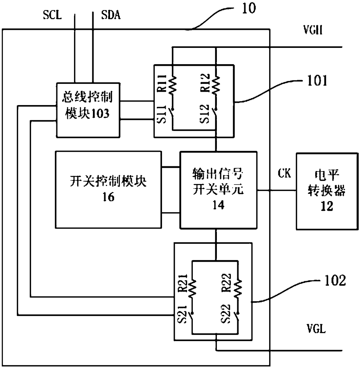
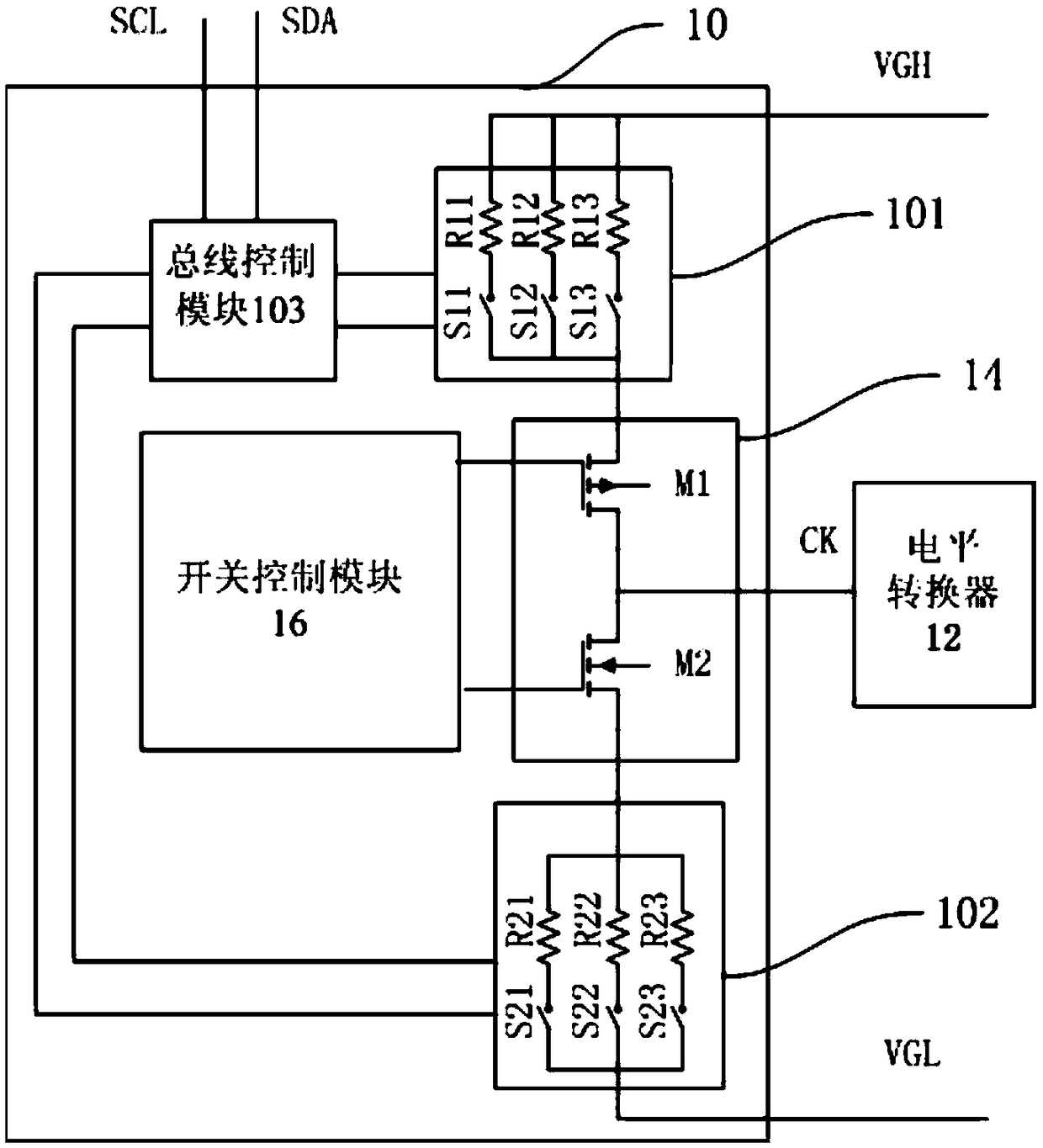
[0014] The output signal control circuit of the present invention is applied to the drive circuit of the liquid crystal panel, the drive circuit includes a level shifter, the input end of the level shifter is used to receive the first voltage signal or the second v...


PUM


Abstract

The invention discloses an output signal control circuit and method and is applied to a driving circuit of a liquid crystal panel. The driving circuit includes a level converter. The circuit and the method are advantaged in that the rising and falling time of an output signal can be adjusted through a bus control module; when different LCD screens are combined, the rising and falling time of the output signal of the level converter can be adjusted based on actual conditions such as the instantaneous peak current and the charging effect, and thereby the magnitude of the instantaneous peak current is adjusted.

Description

technical field [0001] The invention relates to the technical field of liquid crystal display, in particular to an output signal control circuit and a control method capable of adjusting the rise time and fall time of the output signal of a level shifter. Background technique [0002] With the development of optoelectronics and semiconductor technology, panel displays have also developed vigorously. Among many panel displays, TFT-LCD (Thin Film Transistor Liquid Crystal Display), which has superior characteristics such as high space utilization efficiency, low power consumption, no radiation, and low electromagnetic interference, has recently become the mainstream of the market. GOA (Gate Driver on Array, array substrate row drive) technology is to use the existing TFT-LCD array (Array) process to manufacture the gate (Gate) row drive circuit on the array substrate to realize the driving of the gate progressive scan way of a technology. Since the GOA circuit can be directl...

Claims


Application Information

Patent Timeline
Patent Type & Authority Applications(China)
IPC IPC(8): G09G3/36
CPCG09G3/36G09G2310/0243
Inventor 李文芳
Owner TCL CHINA STAR OPTOELECTRONICS TECH CO LTD
Learn More