
Method for generating dozens of megampere pulse currents and z-pinch direct drive source

A technology of pulse current and generation method, applied in circuits, electrical components, transformers, etc., can solve problems such as low voltage utilization, poor maintainability, and poor reliability, and achieve the effects of reducing current loss, reducing impact, and improving reliability

Active Publication Date: 2016-11-09
NORTHWEST INST OF NUCLEAR TECH
View PDF5 Cites 5 Cited by
  • Summary
  • Abstract
  • Description
  • Claims
  • Application Information

AI Technical Summary

Problems solved by technology

[0007] In order to solve the technical problems of low voltage utilization rate, poor reliability and poor maintainability of the existing LTD drive source, the present invention proposes a tens of megaampere-level pulse current generation method and Z-pinch direct drive source

Method used


Image

  • Method for generating dozens of megampere pulse currents and z-pinch direct drive source
  • Method for generating dozens of megampere pulse currents and z-pinch direct drive source
  • Method for generating dozens of megampere pulse currents and z-pinch direct drive source

Examples


Embodiment

[0049] 1) Pulse power source structure

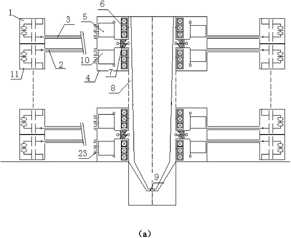
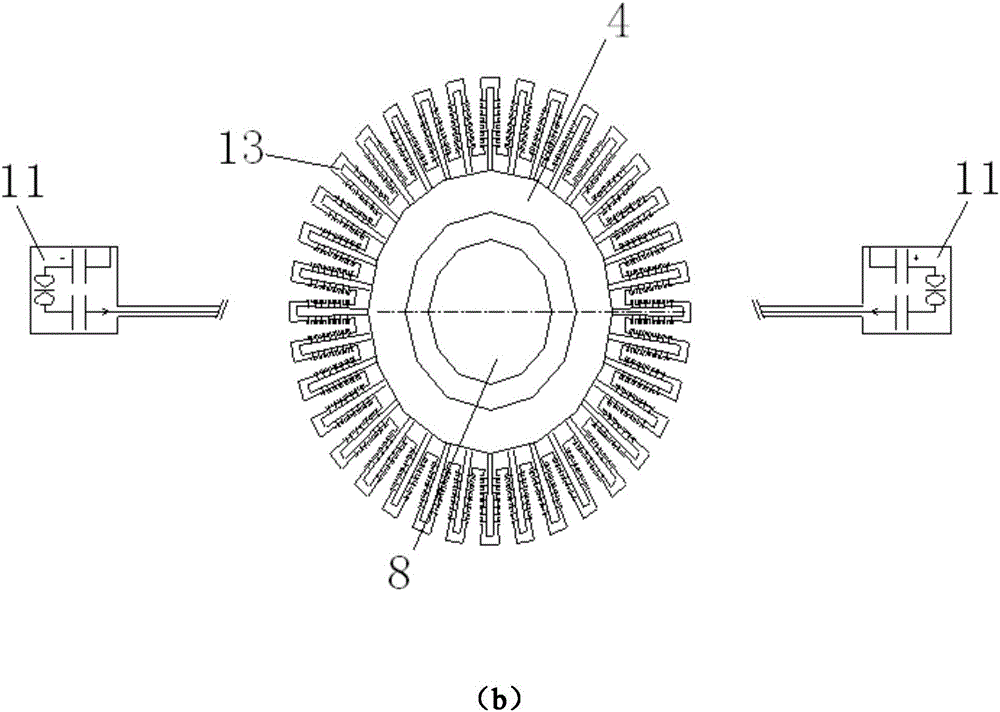
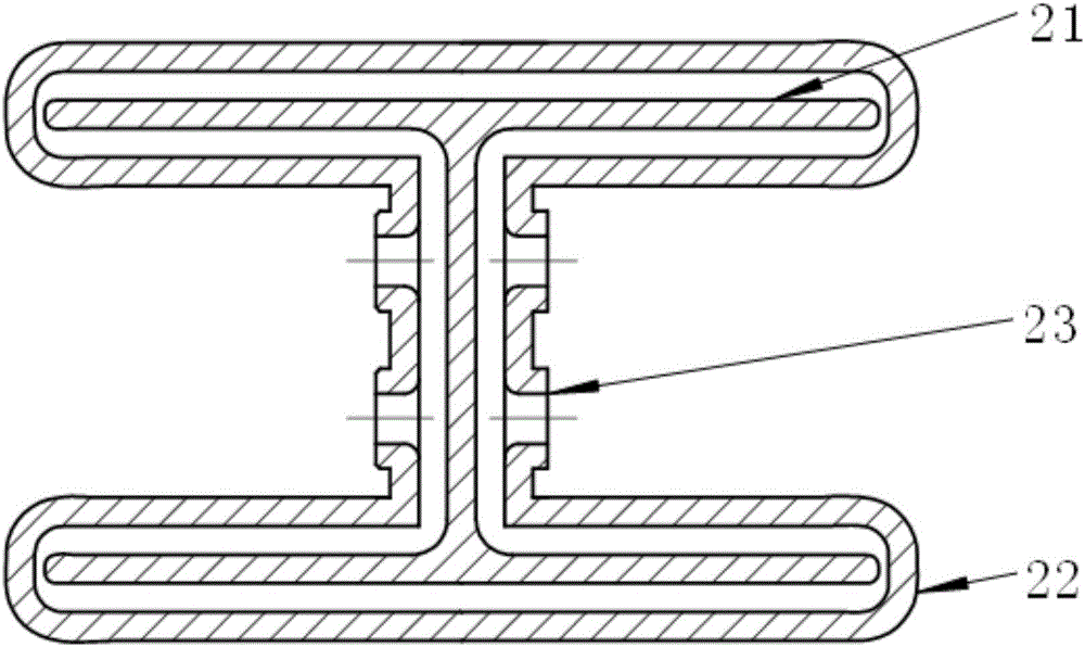
[0050] The primary discharge branch adopts Marx with 2-stage positive and negative polarity charging, 4 plastic case capacitors with a capacity of 80nF double-ended outlets and a working voltage of 100kV, and 2 low-inductance gas switches. The equivalent inductance of the primary discharge branch is 480nH, equivalent The series capacitance is 20nF, and the equivalent series resistance is 0.6Ω. The matching impedance of the above discharge branch is 5.9Ω, and the nominal energy storage is 1.6kJ. When the capacitor is charged at 100kV, each primary discharge branch can provide a 220kV / 37.3kA electric pulse to the matching load. The electrical pulse is transmitted to the I-shaped three-plate transmission line around the induction cavity through an impedance-matched (5.9 hp) high-voltage cable.

[0051] 72 I-shaped three-plate transmission lines are evenly arranged in the upper and lower layers around the induction cavity of each level, 3...


PUM

PropertyMeasurementUnit
diameteraaaaaaaaaa
thicknessaaaaaaaaaa
heightaaaaaaaaaa

Abstract

The invention provides a method for generating dozens of megampere pulse currents and a z-pinch direct drive source. The drive source comprises a primary pulse power source (thousands of fast discharge branch circuits are connected in parallel), a high-voltage transmission cable, a water medium electromagnetic induction chamber, a secondary MITL (Magnetically Insulated Transmission Line) and a z-pinch load, wherein the secondary MITL is formed by connecting multi-stage induction chambers in series; the z-pinch load is located on an axis; thousands of primary discharge branch circuits are located at the peripheries of the induction chambers and are divided into dozens of groups; the primary discharge branch circuits discharge rapidly to directly obtain an electric pulse with a leading edge of 100-200 ns, a voltage of 100-200 kV and a current of 30-50 kA. Currents of the thousands of branch circuits are transmitted and gathered on cable interfaces, which are uniformly distributed at the peripheries of the induction chambers, of dozens of I-shaped tri-plate transmission lines through the cable; the currents are gathered to the induction chambers for primary excitation through the tri-plate transmission lines; and the current gathering is realized through electromagnetic induction. Multi-stage induction chambers are connected in series to form an IVA (Induction Voltage Adder); the MITL is employed for a secondary stage of the IVA to realize voltage superimposition and power transmission; an ultra-high power electric pulse with a voltage of dozens of MV, a current of dozens of MA and a leading edge of 100-200 ns is generated on the Z-pinch load of the axis, and the requirement of a drive current of a Z-pinch ICF (Inertial Confinement Fusion) is met.

Description

technical field [0001] The present invention proposes a petawatt-level (1PW=1000TW) Z-pinch direct drive source that produces a fast front (70-300ns), a current of tens of mA, and a voltage of several MV. Background technique [0002] Pulse power technology is used to generate pulsed large currents of tens of mA to pass through the load (such as wire array or magnetic sleeve MagLIF, Staged Z pinch, etc.). When the current flows in the axial direction, the angular magnetic field pushes the plasma formed by the load inward. The electromagnetic energy is converted into plasma kinetic energy and then converted into soft X-ray radiation energy, and the deuterium-tritium target pellet located in the center of the target chamber is compressed and irradiated to achieve fusion ignition conditions, which is called Z-pinch inertial confinement fusion (abbreviated as Z- ICF); further increase the current and irradiation energy, increase the fusion output, and achieve continuous energy o...

Claims


Application Information

Patent Timeline
Patent Type & Authority Applications(China)
IPC IPC(8): H01F19/08H01F30/06H05H1/04
CPCH01F19/08H01F30/06H05H1/04
Inventor 孙凤举邱爱慈魏浩王志国
Owner NORTHWEST INST OF NUCLEAR TECH
Learn More