Robust phase-locked system and method for grid-connected converter

A converter and phase-locked loop technology, which is applied in the field of grid-connected converter phase locking, that is, grid voltage synchronization, can solve problems such as poor system stability, harmonic amplification of converter systems, and low-frequency oscillation of converters. The effect of convenience, excellent power grid current quality and simple structure

Active Publication Date: 2019-02-12
NANJING UNIV OF AERONAUTICS & ASTRONAUTICS
View PDF3 Cites 3 Cited by
  • Summary
  • Abstract
  • Description
  • Claims
  • Application Information

AI Technical Summary

Problems solved by technology

However, if the grid impedance further increases, the converter system may experience harmonic amplification or even resonance near a lower frequency (close to 100Hz or even down to the fundamental frequency)
In the vicinity of this frequency, the influence of the phase-locked link in the control system of the grid-connected converter is more significant, and an improper phase-locked link is one of the reasons for the low-frequency oscillation of the converter
However, so far, there are still few phase-locked methods for grid-connected converters with strong robustness under weak grid conditions.
[0004] Therefore, in the field of current control of grid-connected converters, in order to solve the problem of poor system stability under large-scale changes in grid impedance, it is necessary to study a grid-connected converter that takes into account stability and current quality, has a simple structure and is easy to implement. Phase-locked grid voltage synchronization method

Method used


Image

  • Robust phase-locked system and method for grid-connected converter
  • Robust phase-locked system and method for grid-connected converter
  • Robust phase-locked system and method for grid-connected converter

Examples


Embodiment Construction

[0032] The technical solutions of the present invention will be described in detail below in conjunction with the accompanying drawings.

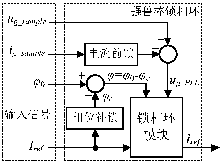
[0033] Such as figure 1 As shown, the present invention provides a robust phase-locked system for grid-connected converters, which is suitable for synchronous control of grid voltage and grid current in grid-connected converter equipment such as single-phase grid-connected inverters, rectifiers, and reactive power compensators. Control; the system includes a current feedforward module, a first subtractor, a second subtractor, a phase compensation module and a phase-locked loop module, wherein the input end of the current feedforward module is used to connect the grid current sampling signal i g_sample , while the output terminal of the current feedforward module is connected to the negative input terminal of the first subtractor, and the positive input terminal of the first subtractor is connected to the grid voltage sampling signal u g_sa...


PUM


Abstract

The invention discloses a robust phase-locked system for a grid-connected converter. The robust phase-locked system comprises a current feed-forward module, a first subtractor, a second subtractor, aphase compensation module and a phase-locked ring module. The invention also discloses a robust phase-locked method for a grid-connected converter. The robust phase-locked method comprises the steps of 1, subtracting a grid voltage sample signal by an output signal of grid current subjected to first-order differentiation element so as to obtain a voltage corrected signal; 2, subjecting a fundamental frequency grid current amplitude reference signal to phase compensation element to generate a phase compensation angle signal, and acquiring a difference between an expected power factor angle signal and the phase compensation angle signal to generate a power factor angle corrected signal; feeding the voltage corrected signal, the power factor angle corrected signal and the fundamental frequency grid current amplitude reference signal to the phase-locked ring module so as to generate an output signal synchronous to grid voltage. The robust phase-locked system and method have the advantagesof great applicability to large-range grid impedance changes, good grid current quality, simple structure and good design convenience.

Description

technical field [0001] The invention belongs to the field of current control of grid-connected converters (including inverters, rectifiers, reactive power compensators, etc.), and particularly relates to a strong robust phase-locked grid-connected converter, that is, a grid voltage synchronization method. Background technique [0002] With the vigorous development of new energy distributed grid-connected power generation, grid-connected converters, as a key part of them, have gained widespread attention. However, converters using pulse width modulation technology generate a large number of switching frequency sub-harmonics. Inserting a filter between the converter and the grid can effectively suppress harmonics. Commonly used filters include L and LCL filters. In order to achieve higher grid-connected power factor and lower grid-side current harmonic distortion, scholars have proposed a large number of grid-connected converter control methods. However, the existing relati...

Claims


Application Information

Patent Timeline
Patent Type & Authority Applications(China)
IPC IPC(8): H02J3/44
CPCH02J3/44
Inventor 许津铭卞申一阳钱强谢少军
Owner NANJING UNIV OF AERONAUTICS & ASTRONAUTICS
Why Eureka
Try Eureka