This helps you quickly interpret patents by identifying the three key elements:
Problems solved by technology
Method used
Benefits of technology
Benefits of technology
The patent text describes a device that can change the electrical connection for three phases of power. This can be done using mechanical switches or power semiconductor switches. The use of power semiconductor switches allows for better electronic control and prevents wear and tear on switch contacts. The device is connected to a grid connection point of an electrical supply grid, which can improve the current quality in the grid.
Problems solved by technology
In this case, grid sections or the grid connection point can sometimes reach a performance limit.
However, it is not only the level of performance that can be problematic, but also the quality of the current, which can be influenced by the charging station.
This can lead to a severe imbalance of the AC system when several vehicles are to be charged.
This accordingly results in an imbalanced load that can affect the electrical supply grid from the charging station.
However, this is unable to take into account the fact that the in-vehicle chargers require different amounts of current depending on the vehicle and state of charge.
If, for example, of six AC charging points, in each case two are provided for the first, two for the second and two for the third phase, an imbalance can still occur if, for example, two vehicles require only a little charging current at both AC charging points in the first phase, whereas two vehicles that require a high charging current are connected to two additional AC charging points for the second phase.
In addition to this, however, a few rapid charging points can be provided if a vehicle in the fleet has to be charged in the meantime and such charging cannot wait until it is charged overnight.
Method used
Image
Click on the blue label to locate the original text in one second.
Reading with bidirectional positioning of images and text.
Examples
example 1
[0110]Charging process with 1 p.u. DC (balanced AC load) and 0.33 p.u. AC to phase A (total current):
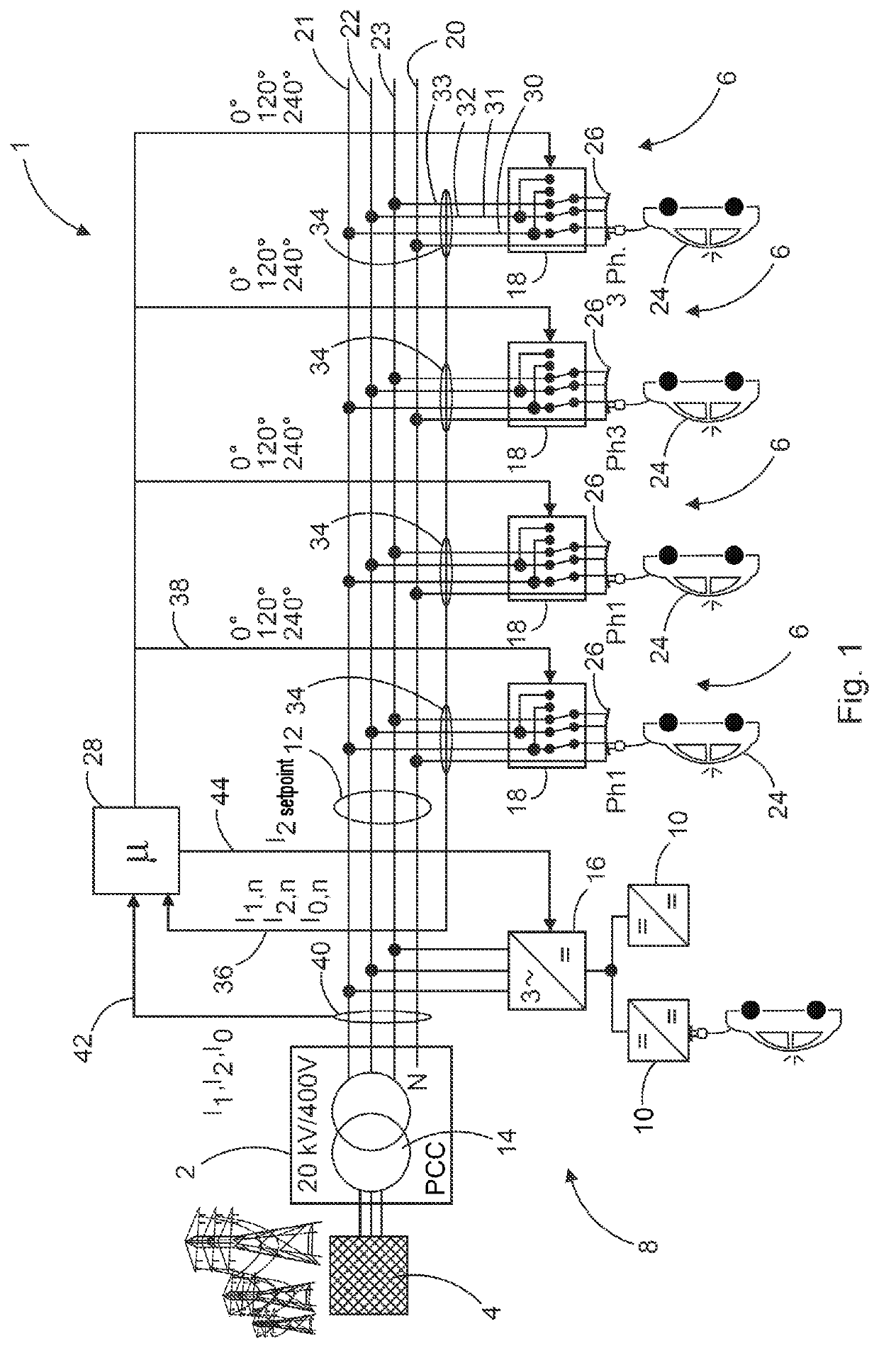
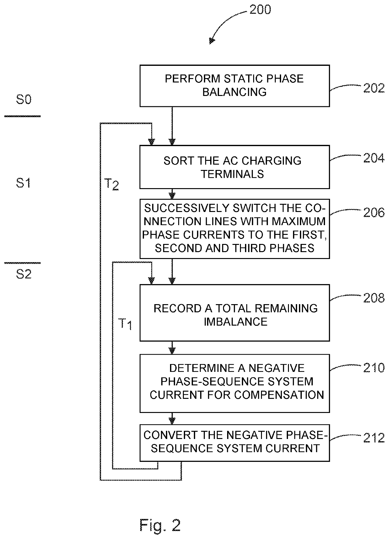
[0115]In example 1, an imbalance of 50% has thus been reduced to 25% by feeding in a negative phase-sequence system current, for example by way of the active rectifier 16 of the embodiment of FIG. 1.
example 2
[0116]Charging process with 1 p.u. DC (balanced AC load) and 4×0.33 p.u. AC to phase A (total current):
[0121]In the 2nd example, there was initially an even greater total imbalance, namely 114%. In a first step, which could correspond to step S1 in FIG. 2, it was reduced to 28% by changing some phase assignments. For this purpos...
PUM
Abstract
A charging station for charging electric vehicles is provided. The charging station includes a plurality of AC charging terminals, each for charging an electric vehicle by means of alternating current. Each of the AC charging terminals is connected to a three-phase power supply via a respective phase-change device in order to be supplied thereby with three-phase electric current. The power supply has three supply lines for providing three voltage phases, and each AC charging terminal has three connection lines for connection to the three supply lines, for applying the three voltage phases to the connection lines. Each phase-change device is set up to change a connection assignment between the three supply lines and the three connection lines.
Description
BACKGROUNDTechnical Field[0001]The present invention relates to a charging station for charging electric vehicles and it also relates to a method for charging electric vehicles.Description of the Related Art[0002]Electric vehicles are becoming increasingly popular and so ever more and ever larger charging stations are required to charge the electric vehicles. Large charging stations, which can also be referred to as electric charging points, can charge many electric vehicles with electricity at the same time. Such a charging station usually receives the power required for this from an electrical supply grid to which it can be connected via a grid connection point. Particularly in the case of large charging stations, their power requirements can have a noticeable impact on the electrical supply grid. In this case, grid sections or the grid connection point can sometimes reach a performance limit.[0003]To counter this, the electrical supply grid and / or the grid connection point can be...
Claims
Application Information
Patent Timeline
Application Date:The date an application was filed.
Publication Date:The date a patent or application was officially published.
First Publication Date:The earliest publication date of a patent with the same application number.
Issue Date:Publication date of the patent grant document.
PCT Entry Date:The Entry date of PCT National Phase.
Estimated Expiry Date:The statutory expiry date of a patent right according to the Patent Law, and it is the longest term of protection that the patent right can achieve without the termination of the patent right due to other reasons(Term extension factor has been taken into account ).
Invalid Date:Actual expiry date is based on effective date or publication date of legal transaction data of invalid patent.

