Three-phase two-level inverter current ripple minimum effective value PWM method and system

A current ripple and inverter technology, applied in the field of three-phase two-level inverter current ripple minimum effective value PWM method and system, can solve the problem of low harmonic distortion rate, increase current ripple, torque Low pulsation and other issues to achieve the effect of reducing loss and improving current quality

Active Publication Date: 2021-04-23
GUANGDONG UNIV OF TECH
View PDF9 Cites 1 Cited by
  • Summary
  • Abstract
  • Description
  • Claims
  • Application Information

AI Technical Summary

Problems solved by technology

[0003] Among them, the simplified algorithm of the classic seven-segment SVPWM (one of which is also called mean value zero-sequence voltage injection PWM) is the most widely used, and has the advantages of high voltage utilization, low harmonic distortion rate, and low torque ripple. These advantages are compared to SPWM, not without room for improvement
Its theory does not analyze the influence of PWM on the current ripple, nor does it explain the application of some degrees of freedom (such as vector selection, zero vector allocation, switching period and pulse position, etc.), so there is room for further improvement
The harmonic injection PWM technology with the third harmonic amplitude coefficient of 1 / 4 has been proved to be the PWM technology that minimizes the current harmonic distortion rate, but it also has the disadvantage of reducing the voltage utilization rate (about 2%)
Overmodulation will occur when it is close to the maximum linear modulation range (0.98~1), which will increase the current THD
Although the five-segment SVPWM method reduces the switching times, it significantly increases the current ripple
The existing PWM technology does not establish a model of PWM and current ripple, and does not make full use of the degree of freedom in the PWM process

Method used


Image

  • Three-phase two-level inverter current ripple minimum effective value PWM method and system
  • Three-phase two-level inverter current ripple minimum effective value PWM method and system
  • Three-phase two-level inverter current ripple minimum effective value PWM method and system

Examples


Embodiment 1

[0077] In order to describe the technical solution of this application in more detail, the current ripple RMS prediction model is described in the actual three-phase two-level inverter system, specifically:

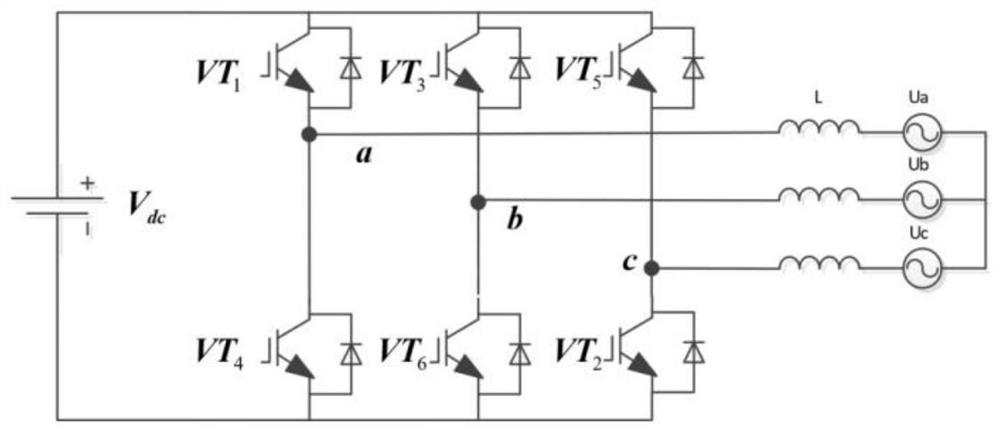
[0078] The topology of the three-phase two-level inverter is as follows figure 1 shown. There are 6 semiconductor switches in the three-phase bridge arms. Each phase bridge arm can only be turned up and down or down and turned on and off. The switching pulses corresponding to this phase are high level (1) and low level (0). When the upper bridge arm is turned on and the lower bridge arm is turned off, the bridge arm ends (points a, b, and c) are connected to the positive pole of the DC bus voltage Vdc / 2, otherwise they are connected to the negative pole -Vdc / 2. The load terminal is replaced by a three-phase symmetrical voltage source, and the current ripple is generated due to the instantaneous voltage difference between the two ends of the inductor.

[0079] Its curren...

Embodiment 2

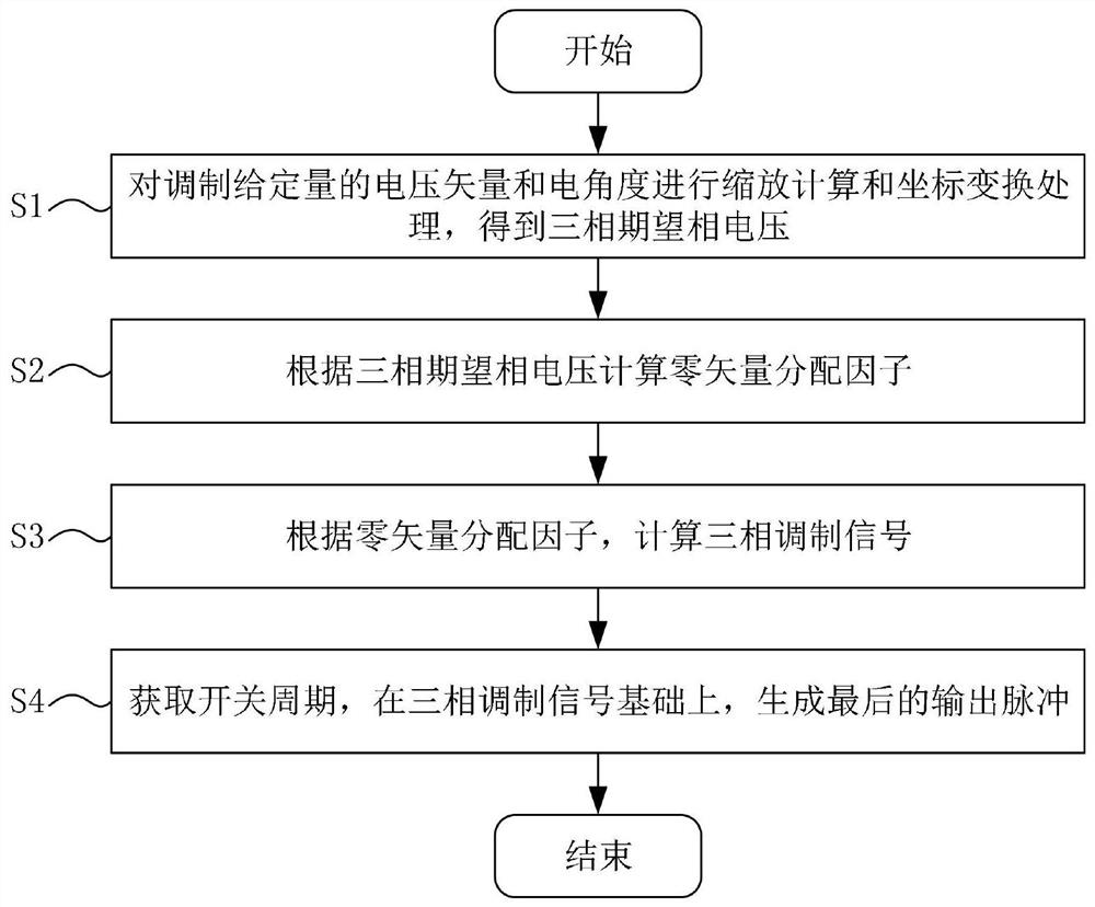
[0104] More specifically, on the basis of Example 1, such as image 3 As shown, the present invention proposes a three-phase two-level inverter current ripple minimum effective value PWM method, comprising the following steps:

[0105]S1: Perform scaling calculation and coordinate transformation processing on the voltage vector and electrical angle of the modulated given amount to obtain the three-phase desired phase voltage;

[0106] S2: Calculate the zero vector distribution factor according to the three-phase expected phase voltage;

[0107] S3: Calculate the three-phase modulation signal according to the zero vector distribution factor;

[0108] S4: Obtain the switching period, and generate the final output pulse on the basis of the three-phase modulation signal.

[0109] In the specific implementation process, the calculation method in step S2 is based on the current ripple RMS prediction model, which establishes a given voltage vector relationship between the current r...

Embodiment 3

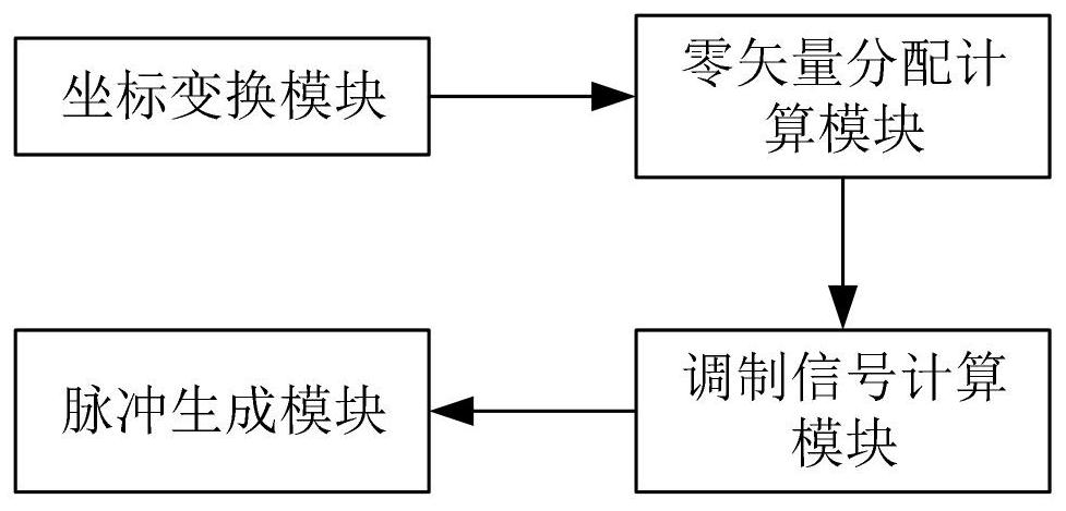
[0138] More specifically, on the basis of Example 2, as Figure 4 As shown, a three-phase two-level inverter current ripple minimum effective value PWM system is provided, including a coordinate transformation module, a zero-vector distribution calculation module, a modulation signal calculation module and a pulse generation module; wherein:

[0139] The coordinate transformation module performs scaling calculation and coordinate transformation processing for the input voltage vector and electrical angle, and generates a three-phase desired phase voltage;

[0140] The zero vector distribution calculation module is based on the current ripple RMS prediction model; with the minimum current ripple RMS as the goal, the zero vector distribution factor is calculated and obtained;

[0141] The modulated signal calculation module is used to calculate the three-phase modulated signal according to the zero vector distribution factor;

[0142] The pulse generating module is used for gen...


PUM


Abstract

According to a three-phase two-level inverter current ripple minimum effective value PWM method and system provided by the invention, a relation between a current ripple RMS and PWM is established by constructing a current ripple RMS prediction model, zero vector distribution is optimized in real time through a calculation result, and finally, a three-phase reference modulation signal is calculated by using an optimized zero vector distribution factor, and an output control pulse is generated. When the current ripple RMS of an inverter is reduced, the current THD and the switching frequency are reduced, the current quality is effectively improved, and the loss is reduced.

Description

technical field [0001] The invention relates to the technical field of pulse width modulation of power electronics technology, and more particularly, to a method and a system for minimum effective value PWM of current ripple of a three-phase two-level inverter. Background technique [0002] With the popularity of industrial automation, voltage source inverters are widely used in industrial and household motors and control fields. The three-phase two-level voltage source inverter is the most widely used due to its low hardware cost, simple structure and mature control theory. At present, the PWM technology used to control the inverter mainly includes the seven-segment SVPWM method, the five-segment SVPWM method and the harmonic injection PWM technology. [0003] Among them, the simplified algorithm of the classic seven-segment SVPWM (one of which is also called mean zero-sequence voltage injection PWM) is the most widely used, and has the advantages of high voltage utilizati...

Claims


Application Information

Patent Timeline
Patent Type & Authority Applications(China)
IPC IPC(8): H02M7/5395H02M7/483H02M1/12H02M1/14
Inventor 谈启伦
Owner GUANGDONG UNIV OF TECH
Why Eureka
Try Eureka