Fractional phase compensation control method and device for LCL grid-connected inverter under weak power grid
A phase compensation and control method technology, applied in the direction of electrical components, circuit devices, AC network circuits, etc., can solve problems such as complex structure of fractional phase compensation strategy, reduction of grid-connected current quality, system phase over-compensation, etc., to achieve suppression of grid harmonics wave and periodic disturbance, improve the quality of grid-connected current, and the effect of simple control structure
- Summary
- Abstract
- Description
- Claims
- Application Information
AI Technical Summary
Problems solved by technology
Method used
Image
Examples
Embodiment 1
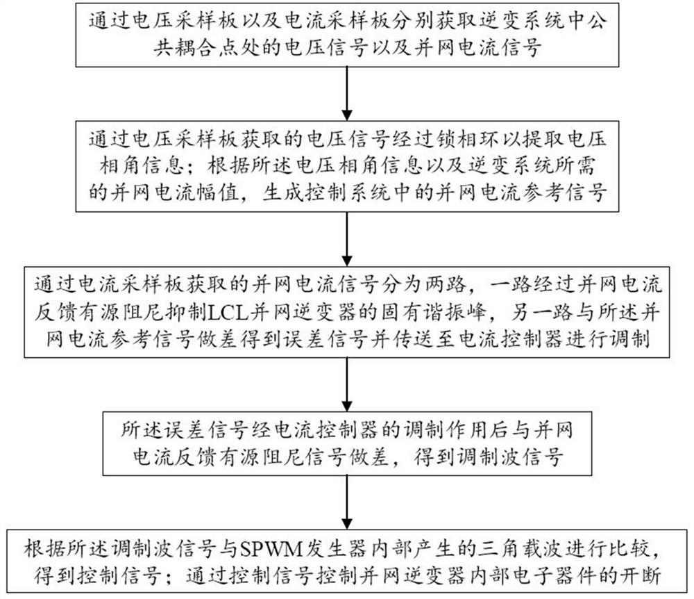
[0044] Such as figure 1 As shown, this embodiment provides a fractional phase compensation control method for an LCL grid-connected inverter under a weak grid, which includes the following steps:
[0045] 1. Obtain the voltage signal at the common coupling point in the inverter system and the grid-connected current signal respectively through the voltage sampling board and the current sampling board;
[0046] 2. The voltage signal obtained through the voltage sampling board passes through the phase-locked loop to extract the voltage phase angle information; according to the voltage phase angle information and the grid-connected current amplitude required by the inverter system, the grid-connected current reference in the control system is generated Signal;
[0047] 3. The grid-connected current signal obtained through the current sampling board is divided into two routes, one route passes through the grid-connected current feedback active damping to suppress the inherent reso...
Embodiment 2
[0072] This embodiment provides a fractional phase compensation control method for an LCL grid-connected inverter under a weak grid, including the following steps:
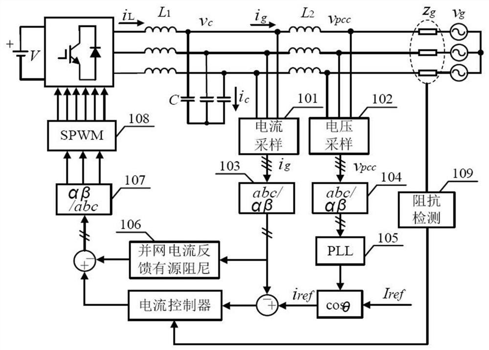
[0073] 1. Obtain the voltage signal at the common coupling point in the inverter system and the grid-connected current signal respectively through the voltage sampling unit 101 and the current sampling unit 102, see figure 2 ;
[0074] 2. The voltage signal at the common coupling point and the grid-connected current signal pass through the first coordinate system transformer 103 and the second The coordinate system converter 104 transforms the three-phase signal into a two-phase signal;
[0075] 3. Pass the second The voltage signal transformed by the coordinate system converter 104 passes through the phase-locked loop PLL105 to extract the voltage phase angle information; according to the phase angle information of the voltage signal and the grid-connected current amplitude required by the inverter syste...
PUM
 Abstract
Description
Claims
Application Information
 - R&D
- Intellectual Property
- Life Sciences
- Materials
- Tech Scout
- Unparalleled Data Quality
- Higher Quality Content
- 60% Fewer Hallucinations
Browse by: Latest US Patents, China's latest patents, Technical Efficacy Thesaurus, Application Domain, Technology Topic, Popular Technical Reports.
© 2025 PatSnap. All rights reserved.Legal|Privacy policy|Modern Slavery Act Transparency Statement|Sitemap|About US| Contact US: help@patsnap.com


