
3D printed vascular stent

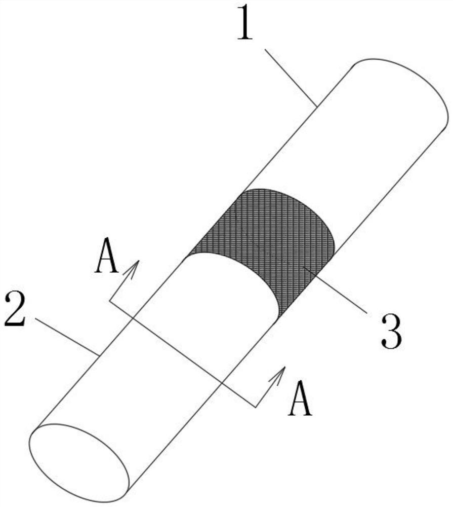
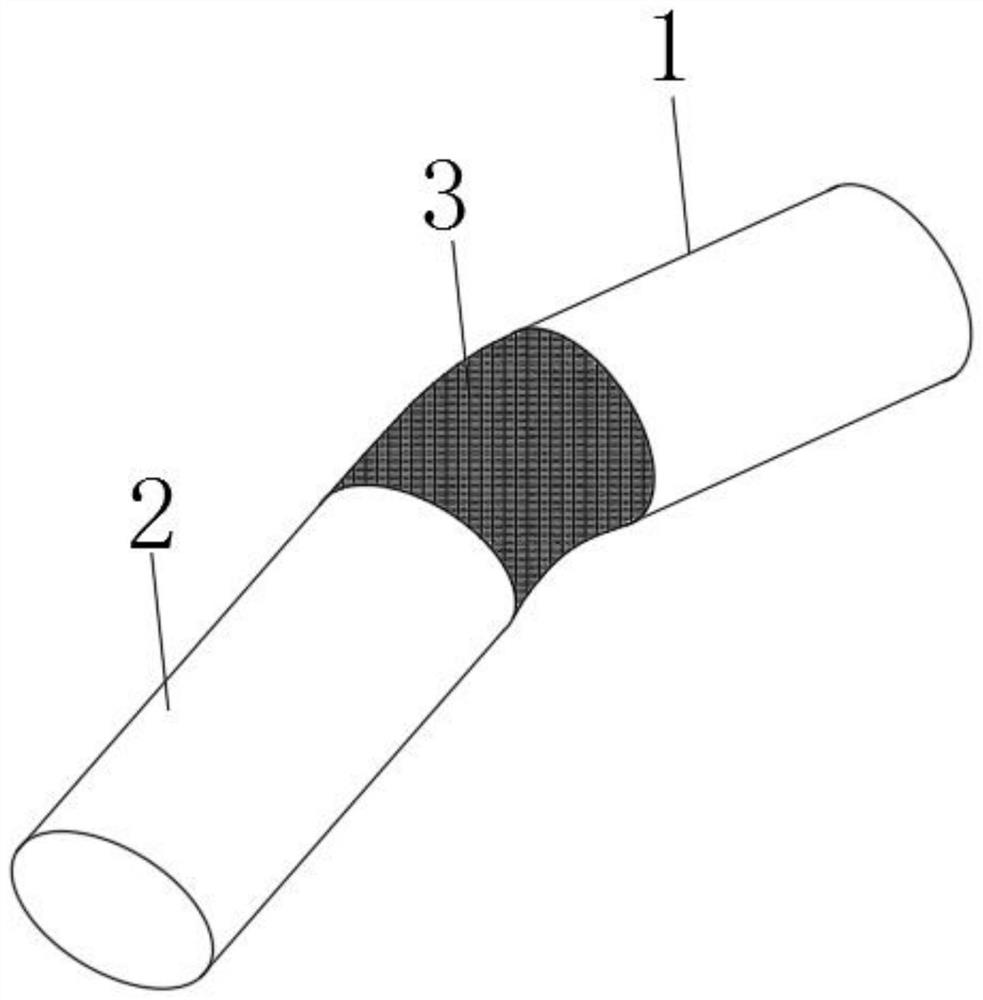
A 3D printing and vascular stent technology, applied in the field of vascular stents, can solve problems such as poor bending adaptability, and achieve the effects of improving adaptability, avoiding blood coagulation, and prolonging anticoagulation time.

Active Publication Date: 2020-12-29
THE FIRST AFFILIATED HOSPITAL OF ARMY MEDICAL UNIV
View PDF10 Cites 0 Cited by
  • Summary
  • Abstract
  • Description
  • Claims
  • Application Information

AI Technical Summary

Problems solved by technology

[0005] In view of this, the purpose of the present invention is to provide a 3D printed vascular stent, which adopts a special structural design, so that the stent has a strong bending ability, and the direction is not limited, and can be adapted to be placed on any part of the blood vessel, solving the problem of The existing technology cannot bend the problem of poor adaptability

Method used


Image

  • 3D printed vascular stent
  • 3D printed vascular stent
  • 3D printed vascular stent

Examples


no. 1 example

[0043] Such as Figure 6 As shown, the front part of the stent, the back part of the stent and the connecting part are all porous mesh structures. Specifically, the connecting part is a porous circular straight tube made by 3D printing, and the two ends of the porous circular straight tube are respectively connected and fixed to the front section of the bracket and the back section of the bracket.

no. 2 example

[0045] Such as Figure 7 , Figure 8 , Figure 9 As shown, the front section of the bracket and the back section of the bracket are porous mesh structures, and the connecting part is a wire harness made by 3D printing. The number of wire harnesses is not limited. Figure 7 , Figure 8 , Figure 9 The cases of one, two and four are shown respectively.

[0046] Of course, the wire harness in this embodiment can also be obtained without printing.

no. 3 example

[0048] Such as Figure 10 As shown, the front section of the bracket and the back section of the bracket in this embodiment are both cylindrical columnar structures, and the connecting part is a porous network structure. The cylindrical columnar structure is composed of a ring beam 7 and a support beam 8, and the ring beam and the support beam Multiple ring beams are arranged in parallel, and multiple support beams are arranged in parallel and evenly distributed on the circumference of any ring beam. The specific values ​​of the width and thickness of the ring beams and support beams in this embodiment are not limited. , but at least its width / thickness is required to be greater than 1, which can make it have strong elasticity and have a better supporting effect on blood vessels, so that compared with the prior art, it can reduce the contact area with blood, reduce blood coagulation and even re- Risk of blood clots.

[0049] Through further optimization, this embodiment propo...


PUM


Abstract

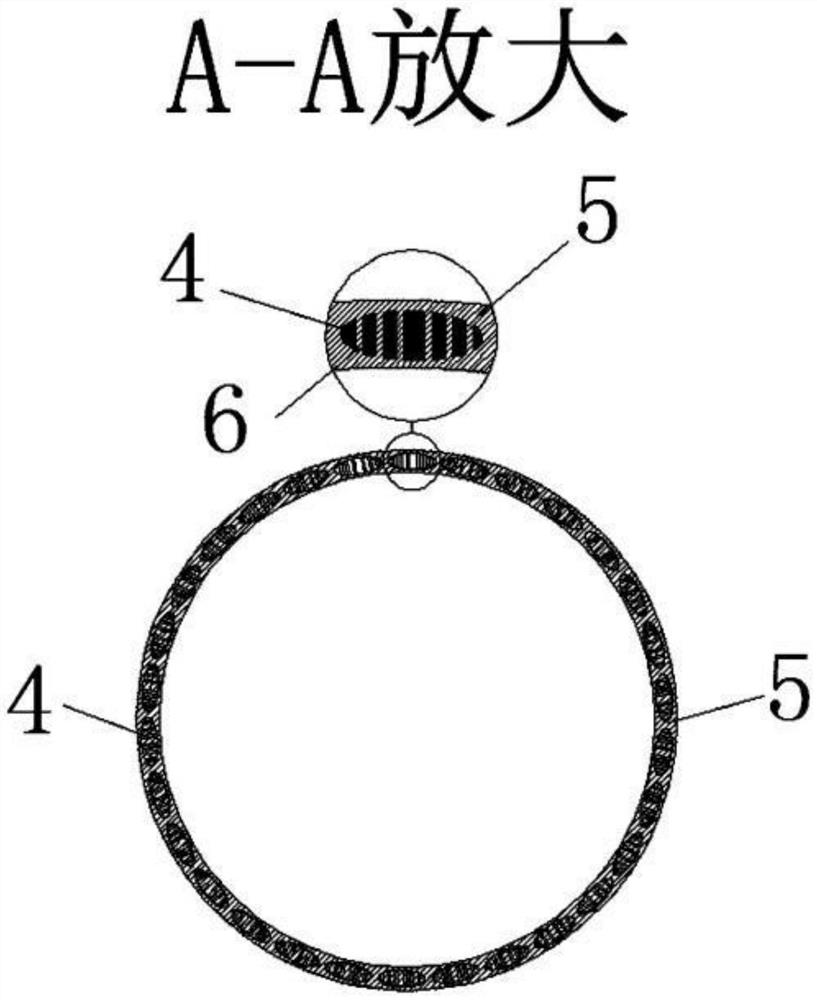
The invention relates to a 3D printed vascular stent, and belongs to the technical field of devices for providing an opening for or preventing the collapse of the tubular structure of the human body.The 3D printed vascular stent comprises a front stent section, a rear stent section and a bendable connecting part, wherein the front stent section and the rear stent section are made through 3D printing, and the connecting part is arranged between the front stent section and the rear stent section; the connecting part, the front stent section and the rear stent section are all of a double-layer structure comprising an inner supporting layer and an outer anti-coagulation layer, wherein the inner supporting layer is of a porous net structure, and the outer anti-coagulation layer is embedded innet holes of the inner supporting layer. The stent is arranged into a combined structure of the front stent section and the rear stent section, the front stent section and the rear stent section can rotate mutually through the bendable connecting part, then bending of the stent is realized, the stent can be placed on a bent portion of the blood vessel, and the adaptability is improved.

Description

technical field [0001] The invention relates to the technical field of devices for providing openings or preventing collapse of tubular structures of the human body, and in particular to a vascular stent with strong adaptability to 3D printing. Background technique [0002] With the improvement of living standards, people's life expectancy is generally on the rise. However, with the prolongation of life expectancy, the risk of cardiovascular disease also increases sharply, seriously perplexing people's life. For severe patients, the existing technology basically uses stents to support or expand the inner wall of blood vessels to reduce the intravascular pressure and improve blood flow capacity, so as to alleviate or treat cardiovascular diseases. [0003] The construction of existing scaffolds mainly includes acellular matrix method, cell membrane method, microfluidic method, electrospinning and 3D printing and other technologies. 3D printing method and electrospinning hav...

Claims


Application Information

Patent Timeline
Patent Type & Authority Patents(China)
IPC IPC(8): A61F2/90A61L27/06A61L27/50A61L33/04A61L33/08B33Y10/00
CPCA61F2/90A61L27/06A61L27/507A61L33/04A61L33/08A61L2300/216A61L2300/418A61L2300/606
Inventor 胡俊王富友袁继超范华全李光建赵欢李颖
Owner THE FIRST AFFILIATED HOSPITAL OF ARMY MEDICAL UNIV
Learn More