Full-automatic medical drainage device

A fully automatic, drainage tube technology, applied in the field of medical devices, can solve the problems of increasing the burden on medical staff and patients' families, failing to follow the doctor's expected method, and difficult to guarantee the drainage effect, so as to improve safety, stability and drainage effect. Guaranteed and reduced workload

Active Publication Date: 2019-02-15
滨州医学院附属医院 +1
View PDF11 Cites 0 Cited by
  • Summary
  • Abstract
  • Description
  • Claims
  • Application Information

AI Technical Summary

Problems solved by technology

[0003] In the clinical operation of drainage of a large amount of effusion, there are often specific requirements for clinical parameters such as daily drainage times, each drainage volume, and drainage speed according to the condition of the case. The parameters are usually controlled subjectively by the medical staff or the patient's family members. The current artificial control method has certain disadvantages. As a result, the drainage process cannot be carried out in the way the doctor expected, and the improper drainage will cause discomfort and injury to the patient, and even endanger the patient's life. On the other hand, the real-time drainage volume and drainage speed during the drainage process are usually determined by human observation. Judgment, the error is large, and it is difficult to guarantee the drainage effect. At the same time, the current control method will obviously increase the burden on the medical staff and the patient's family members.
[0004] The drainage bag is a relatively cheap medical product, and it is the best choice as the terminal container in clinical effusion drainage, but it can only be applied to conventional pleural effusion drainage operations under normal pressure, and cannot be applied to negative pressure drainage. Negative pressure drainage usually requires the use of water-sealed bottles that are more expensive than drainage bags, which brings a certain economic burden to patients

Method used


Image

  • Full-automatic medical drainage device
  • Full-automatic medical drainage device
  • Full-automatic medical drainage device

Examples


Embodiment 1

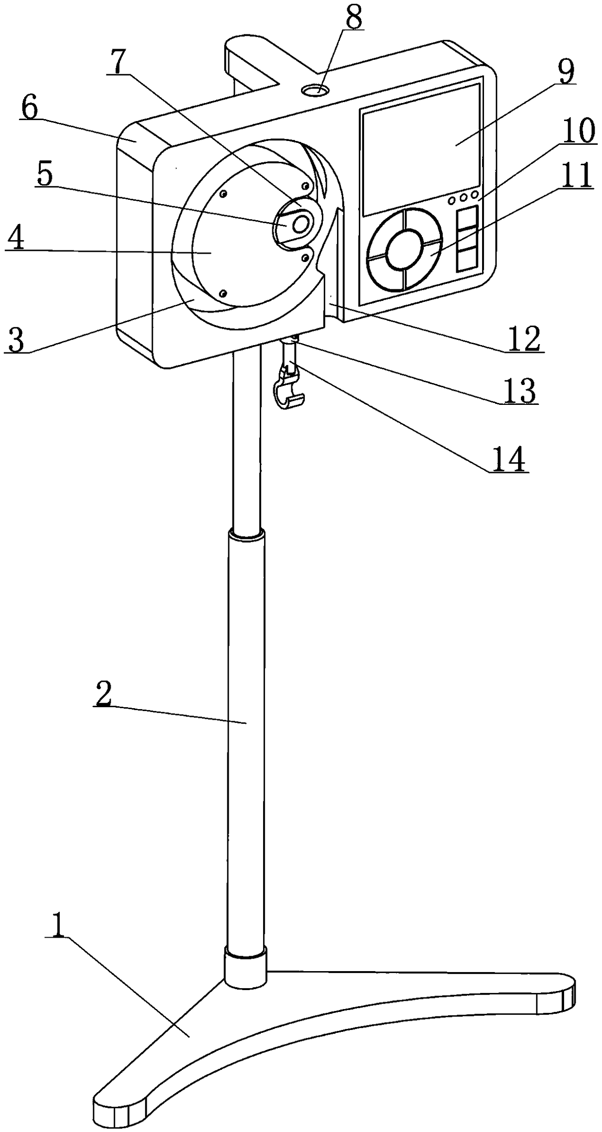
[0043] See figure 1 , 2 As shown, this embodiment discloses a fully automatic medical drainage device, which is composed of a support assembly, a weighted suspension assembly, a drainage adjustment assembly, a controller 10 and a power supply assembly 15;

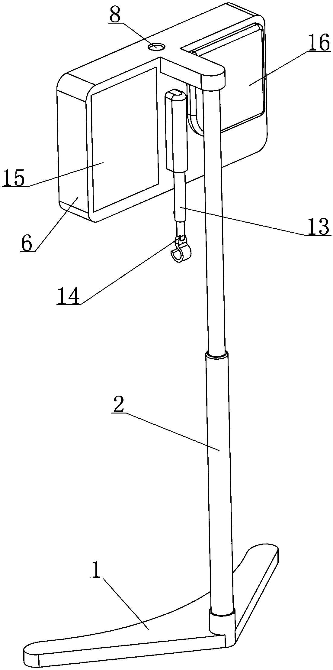
[0044] Among them, see figure 1 , 2 As shown, the support assembly is composed of a base 1, a column 2 and a mounting plate 6. The column 2 is supported by the base 1 and extends in a vertical direction. The mounting plate 6 is supported by the upper end of the column 2 and is located above the base 1 and the column. The front side of 2; the placement plate 6 is used to provide support and installation space for other components;

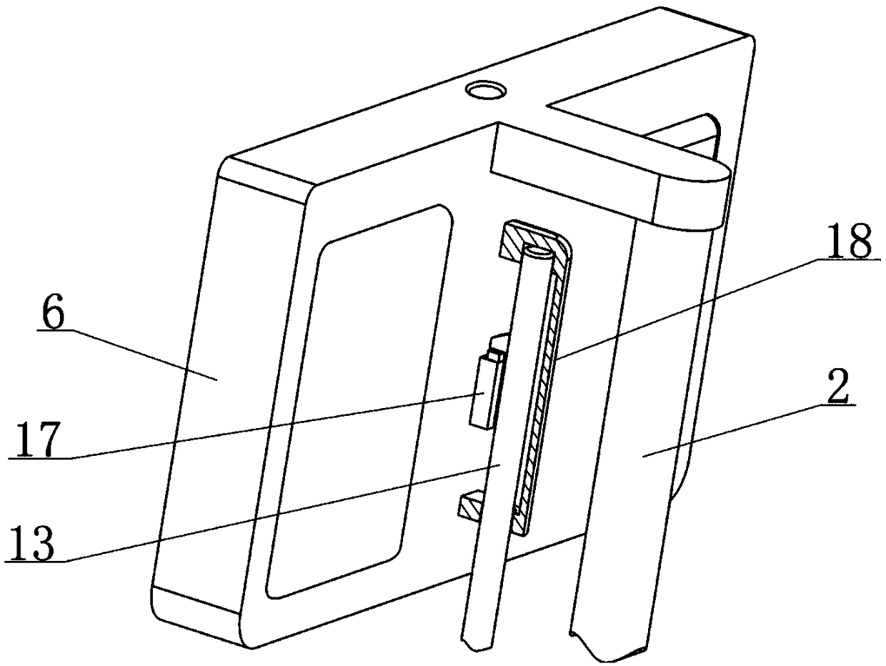
[0045] Among them, see figure 2 , 3 , 11, 12, the weighing type suspension assembly includes a weighing rod 13, a weighing sensor 17, and a suspension 14; the upper part of the weighing rod 13 is limited by the placement plate 6 so that the weighing rod 13 extends up and down The load cell 17 is supp...

Embodiment 2

[0080] See Figure 4 , 8 As shown, in the fully automatic medical drainage device disclosed in the foregoing embodiment, the cross-section of the introduction hole 8 is circular, so as to ensure the integrity of the side wall of the recess 3 to the greatest extent. Hole structure, when the drainage tube 29 is introduced into the annular gap, the tail end of the drainage tube 29 needs to be passed through the introduction hole 8 from front to back, which is not convenient enough; for this reason, this embodiment is based on the embodiment 1. The placement board 6 has the following improvements:

[0081] Such as Figure 13 , 14 As shown, the mounting plate 6 has a square groove 33 on the front side wall that can completely expose the introduction hole 8. The square groove 33 defines a sliding baffle 32 with a moving stroke; when the sliding baffle 32 is in its stroke At the beginning, it blocks the front side of the introduction hole 8 and can compress the drainage tube 29 in the i...

Embodiment 3

[0084] See Picture 11 As shown, in the clinical use of the fully automatic medical drainage device disclosed in the foregoing embodiments, its specific installation position is determined by the position of the patient and the arrangement of the drainage assembly, and often its location is not conducive to the operation of the operator It is not conducive for the operator to know the drainage status by observing the display screen 9 by pressing the key to perform parameter presets, etc., which brings certain inconvenience to the clinical drainage operation; in order to solve this defect, this embodiment is disclosed in the previous embodiment Based on the structure of the fully automatic medical drainage device, there are further improvements, the specific structure is as follows:

[0085] Such as Figure 15 As shown, the fully automatic medical drainage device is equipped with a remote control device, the remote control device is equipped with a wireless transmission module, a d...


PUM


Abstract

The invention relates to the field of medical apparatuses, and discloses a full-automatic medical drainage device. The full-automatic medical drainage device is composed of a support assembly, and a weighing type hanging and supporting assembly, a drainage adjusting assembly, a controller and a power supply assembly which are supported by the support assembly. The weighing type hanging and supporting assembly can provide support for a drainage bag and feed weight signals for reflecting the accumulated liquid weight variation state back to the controller. The drainage adjusting assembly can extrude the drainage pipe in different ways to adjust the drainage state. The controller can control the working state of the drainage adjusting assembly on the basis of the obtained weight signals, thepreset drainage mode and drainage parameters. The full-automatic medical drainage device can automatically control the regular drainage, quantitative drainage and speed-fixed drainage when used in cooperation with an existing conventional drainage assembly by means of the intelligent design, improves the safety and stability of drainage operation, has a normal-pressure drainage mode and a negative-pressure drainage mode, can meet most of the clinical drainage requirements, and has wide application prospects clinically.

Description

Technical field [0001] The invention relates to the technical field of medical devices, and in particular to a fully automatic medical drainage device capable of automatically controlling the drainage process. Background technique [0002] Under normal conditions, there is a small amount of fluid in the thoracic cavity and abdominal cavity of the human body, which lubricates the organs in the cavity. If the amount of fluid in the cavity increases beyond the normal physiological range under pathological conditions, it will become a disease, such as pleural fluid and ascites. There are many causes of ascites and pleural effusions, which are very common clinical symptoms. Although ascites and pleural effusions are only a symptom, large amounts of ascites and pleural effusions can cause a series of complications The disease is not conducive to the treatment of the cause, and even life-threatening in severe cases. Therefore, for cases with a large amount of abdominal effusion and a ...

Claims


Application Information

Patent Timeline
Patent Type & Authority Applications(China)
IPC IPC(8): A61M1/00
CPCA61M2205/3334
Inventor 王才丰
Owner 滨州医学院附属医院
Why Eureka
Try Eureka