Shunting system with pneumatic shunting well and control method

A diverting system and diverting well technology, applied in waterway systems, sewage removal, drainage structures, etc., can solve the problem of high cost of electronically controlled hydraulic control, and achieve mature and reliable prices, cost savings, and low costs.

Pending Publication Date: 2019-02-15
WUHAN SHENGYU DRAINING SYST
View PDF0 Cites 2 Cited by
  • Summary
  • Abstract
  • Description
  • Claims
  • Application Information

AI Technical Summary

Problems solved by technology

[0005] In view of the safety problems of electronic control and the high cost of hydraulic control in the prior art, the inventor considered the device using compressed air as the power source

Method used


Image

  • Shunting system with pneumatic shunting well and control method
  • Shunting system with pneumatic shunting well and control method

Examples


Embodiment 1

[0072] A diversion system with a pneumatic diversion well 40, used to divert the fluid in the drainage pipe, wherein the drainage pipe is a drainage pipe in a confluence system, a diversion system or a mixed flow area or in front of an outlet near a natural water body piping, including:

[0073] Compressed gas source 10, used to provide compressed gas;

[0074] Gas delivery pipe, the gas delivery pipeline is used to deliver gas;

[0075] Pneumatic diverter well 40,

[0076] The pneumatic diversion well 40 includes a well body structure and at least an inlet 411 arranged on the well body structure, a first water outlet pipe 413, a second water outlet pipe 412 and a pneumatic shut-off device arranged on the second water outlet pipe 412, which is the second water outlet pipe 412. Two pneumatic shut-off devices 422, wherein the inlet 411 is connected to the drainage pipe upstream of the pneumatic diversion well 40, the first water outlet pipe 413 is connected to the rainwater pi...

Embodiment 2

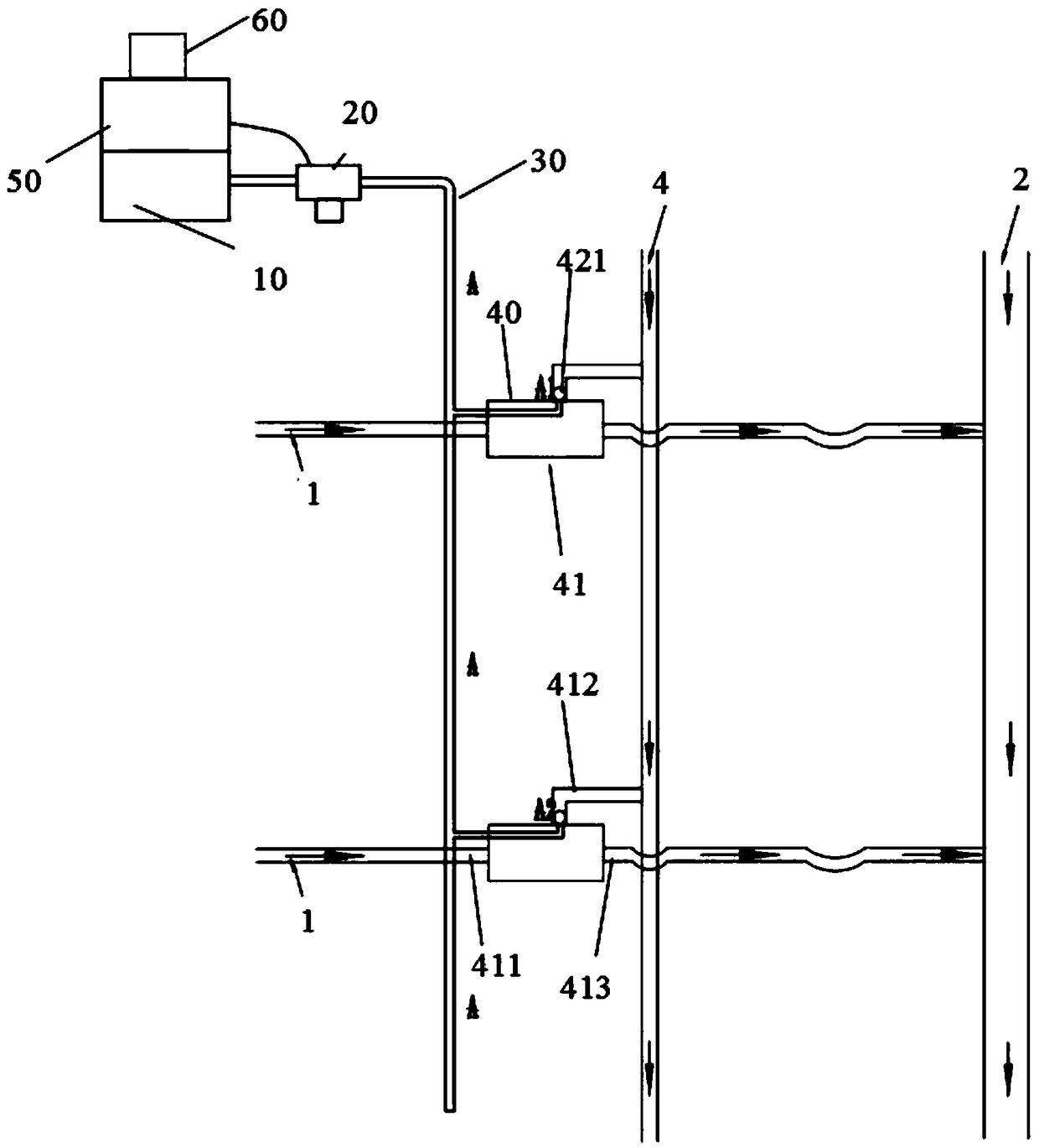
[0112] figure 1 It is a schematic structural diagram of a one-input and two-outlet cell distribution system applied to a distribution system cell, a combination system cell or a mixed flow system cell according to an embodiment of the present invention.

[0113] see figure 1 As shown, the form of the pneumatic diversion well is form one, including compressed gas source 10, control valve 20, gas delivery main pipe 30, pneumatic diversion well 40, controller 50, measuring instrument 60, rainwater pipe and sewage pipe 4 through the outlet pipe 1. The sewage intercepting pipe 3 communicates with the pneumatic shunt well 40 .

[0114] A compressed gas source 10 is used to provide compressed gas. In this embodiment, the compressed gas source is an air compressor, which is set in the control room of the community.

[0115] The control valve 20 is connected with the compressed gas source at the inlet. When an air bag or a pneumatic pipe pinch valve structure is arranged in the pneum...

Embodiment 3

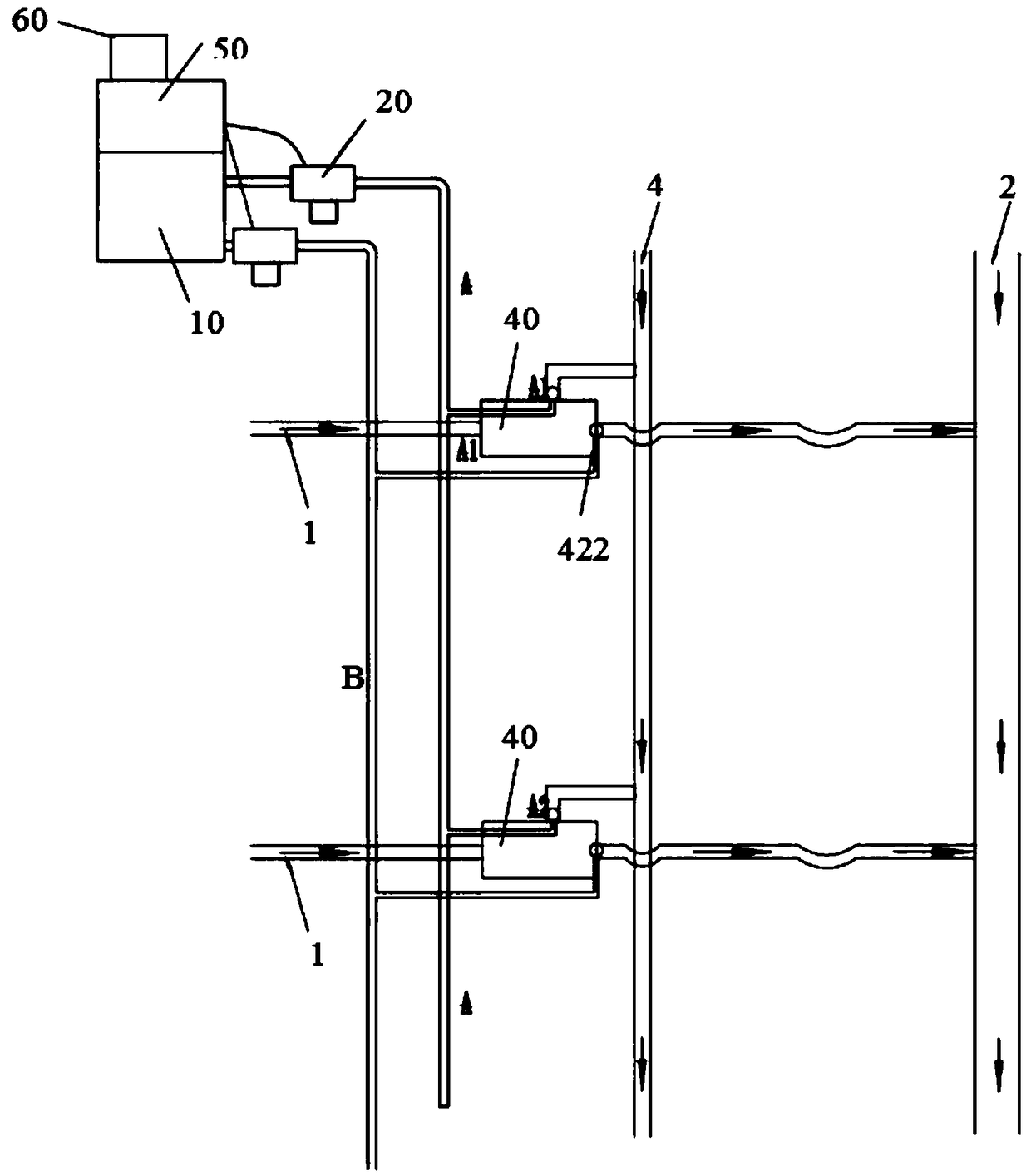
[0125] figure 2 It is a schematic structural diagram of a one-inlet and two-outlet community distribution system in Embodiment 3 of the present invention. The form of the pneumatic splitter well in this embodiment is form two.

[0126] Such as figure 2 As shown, the difference between the present embodiment and the second embodiment is that two pneumatic shut-off devices are respectively provided at the first water outlet pipe 413 and the second water outlet pipe 412 of the pneumatic diverter well, respectively the first pneumatic shut-off device 421 and the second pneumatic shut-off device. The shut-off device 422, its pneumatic shut-off device selects air bag or pneumatic pipe pinch valve for use. Correspondingly, two control valves should be set: the first control valve and the second control valve, and the number of gas delivery main pipes is also two: the first gas delivery main pipe and the second gas delivery main pipe, and the first control valve controls The firs...


PUM


Abstract

The invention provides a shunting system with pneumatic shunting well, which is used for shunting the fluid in a drainage pipe and comprises a compressed gas source, a gas conveying pipe and the pneumatic shunting well. The pneumatic shunting well comprises a well structure, at least an inlet, a first water outlet pipe and a second water outlet pipe arranged on this well structure, and a pneumaticcut-off device arranged on the second water outlet pipe as the second pneumatic cut-off device, wherein the inlet is communicated with a drain pipe at the upstream of the pneumatic shunting well, thefirst water outlet pipe is communicated with a rainwater pipe or a natural water body at the downstream of the pneumatic shunting well, and the second water outlet pipe is communicated with a sewagepipe or a sewage treatment facility or a detention tank or an initial rainwater pipe or a detention tank or an initial rainwater treatment facility. A control valve comprises a second control valve arranged on the gas conveying pipe, wherein the second control valve controls the charging and the discharging of the second pneumatic cut-off device and is used for controlling the turn-on and turn-offof the corresponding second water outlet pipe. The drain pipes are those in the areas of confluence, diversion or mixed flow or the pipelines in front of the outlet close to the natural water body.

Description

technical field [0001] The invention relates to diversion of rainwater and sewage, in particular to a diversion system with a pneumatic diversion well and a control method, belonging to the technical fields of civil buildings and water supply and drainage. Background technique [0002] At present, in the pneumatic diversion well, abandonment well and interception well system, the system is composed of water inlet pipe, outlet pipe and sewage pipe, which divert the domestic sewage in the drainage pipe or the initial rainwater and later rainwater. Or the initial rainwater is intercepted to the sewage pipe and then transported to the sewage treatment plant for treatment and discharged after reaching the standard (further, the initial rainwater can be stored or intercepted to the sewage treatment plant for treatment and discharged after reaching the standard). in a body of water. [0003] In reality, the devices that realize the cut-off and conduction functions in pneumatic div...

Claims


Application Information

Patent Timeline
IPC IPC(8): E03F1/00E03F5/10
CPCE03F1/00E03F5/10E03F5/101E03F5/105E03F5/107E03F2201/00
Inventor 周超李习洪
Owner WUHAN SHENGYU DRAINING SYST
Why Eureka
Try Eureka