Air conditioner indoor unit and air conditioner

An air-conditioning indoor unit and indoor unit technology, applied in air-conditioning systems, space heating and ventilation, space heating and ventilation details, etc., can solve the problem of low utilization rate of condensed water cooling capacity, achieve compact structure, high utilization rate, The effect of improving cooling efficiency

Pending Publication Date: 2019-02-15
QINGDAO HAIER AIR CONDITIONING ELECTRONICS CO LTD
View PDF0 Cites 5 Cited by
  • Summary
  • Abstract
  • Description
  • Claims
  • Application Information

AI Technical Summary

Problems solved by technology

[0006] In order to solve the above-mentioned problems in the prior art, that is, in order to solve the problem that the existing air conditioner has a low utilization rate of the cooling capacity in the condensed water generated by the indoor unit, the first aspect of the present invention provides an air conditioner indoor unit, the indoor unit It includes an air supply channel and an evaporator arranged in the air supply channel, and the indoor unit also includes: a water receiving tray, which is arranged under the evaporator, and is used to receive the condensed water flowing out of the evaporator; a water pump, It is used to pump the condensed water in the water receiving tray; the condensed water pipe, the inlet of which is connected to the water outlet of the water pump, the condensed water pipe includes a heat exchange pipe section, and the heat exchange pipe section is arranged on the delivery pipe in the air passage for heat exchange with the air in the air supply passage

Method used


Image

  • Air conditioner indoor unit and air conditioner
  • Air conditioner indoor unit and air conditioner

Examples


Embodiment Construction

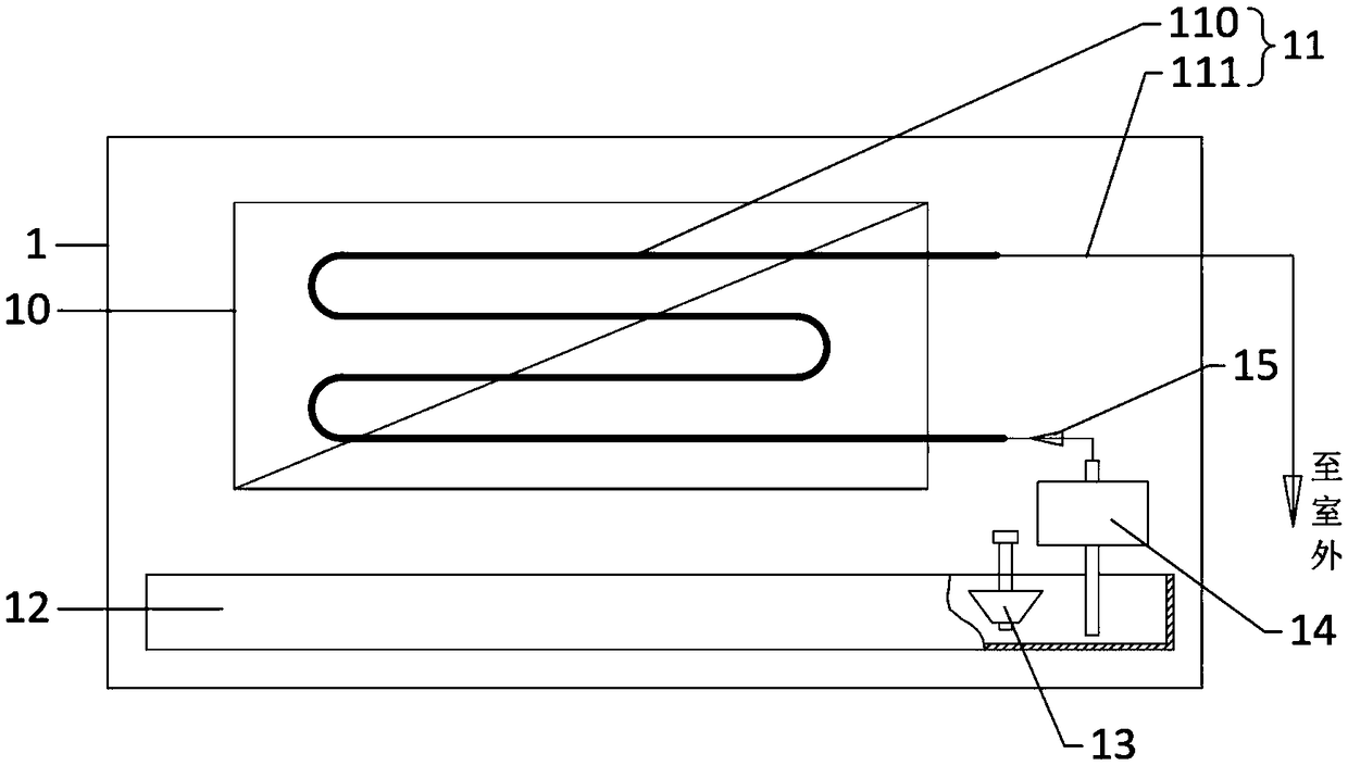
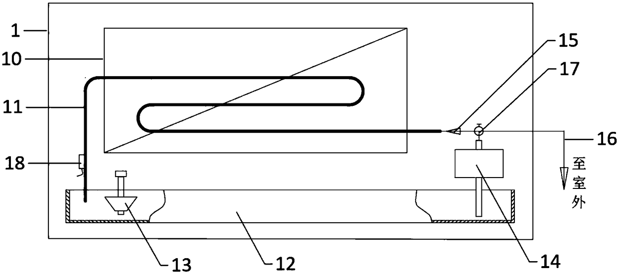
[0034] Preferred embodiments of the present invention are described below with reference to the accompanying drawings. Those skilled in the art should understand that these embodiments are only used to explain the technical principles of the present invention, and are not intended to limit the protection scope of the present invention. For example, although the following implementations are explained in conjunction with domestic air conditioner indoor units, this is not limiting. The technical solution of the present invention is also applicable to commercial air conditioners, such as multi-connected air conditioner systems. changes without departing from the principles and scope of the present invention.

[0035] In addition, in order to better illustrate the present invention, numerous specific details are given in the specific embodiments below. It will be understood by those skilled in the art that the present invention may be practiced without certain of the specific det...


PUM


Abstract

The invention relates to the technical field of air conditioners and aims to solve the problem that existing air conditioners have low utilization rate of the cooling capacity in condensate water generated by indoor units, and for this reason, the invention provides an air conditioner indoor unit and an air conditioner. The indoor unit comprises an air supply passage and an evaporator arranged inside the air supply passage and further comprises a water receiving tray, a water pump and a condensate water pipeline, wherein the water receiving tray is arranged below the evaporator and used for receiving the condensate water flowing out of the evaporator; the water pump is used for pumping and conveying the condensate water inside the water receiving tray; and an inlet of the condensate waterpipeline is connected to a water outlet of the water pump, the condensate water pipeline comprises a heat exchanging pipe segment, and the heat exchanging pipe segment is arranged inside the air supply passage to perform heat exchanging with air inside the air supply passage conveniently. By means of the air conditioner indoor unit and the air conditioner, the cooling capacity in the condensate water generated by the indoor unit can be utilized sufficiently, the air conditioning refrigeration efficiency is improved, cooling capacity waste is avoided, special equipment of a long distance transportation pipeline is not needed, and the air conditioner indoor unit and the air conditioner are low in cost and good in effect.

Description

technical field [0001] The invention relates to the technical field of air conditioners, in particular to an air conditioner indoor unit and an air conditioner. Background technique [0002] During the cooling process of the air conditioner in summer, the evaporator located in the indoor unit will produce condensed water during the heat exchange with the air. The temperature of the condensed water is much lower than the temperature of the indoor air, and the cooling capacity contained in it can be recycled. value. [0003] Some existing air conditioners usually drain the condensed water directly through the drain pipe without recycling it, resulting in a waste of cooling capacity; some air conditioners collect the condensed water and transport it to the condenser in the outdoor unit through pipelines , used to absorb the heat of the refrigerant in the condenser, accelerate the heat dissipation of the condenser, and realize the recovery and reuse of cold energy. [0004] Ex...

Claims


Application Information

Patent Timeline
Patent Type & Authority Applications(China)
IPC IPC(8): F24F1/0067F24F13/22
CPCF24F1/0059F24F13/222
Inventor 任善军毛守博何建奇远义忠王洪伟
Owner QINGDAO HAIER AIR CONDITIONING ELECTRONICS CO LTD
Why Eureka
Try Eureka