
Feedback control method and system for electronic accelerator irradiation system

An electron accelerator and feedback control technology, applied in irradiation devices, nuclear engineering, etc., can solve problems such as stability and accuracy of drift irradiation products, unstable beam current value, and high-precision control

Inactive Publication Date: 2019-02-15
房春
View PDF6 Cites 4 Cited by
  • Summary
  • Abstract
  • Description
  • Claims
  • Application Information

AI Technical Summary

Problems solved by technology

[0009] The electron beam current signal at the high-voltage end in the power supply steel barrel is sampled by the electron beam current sampling circuit to obtain a downlink voltage signal, and the electron beam current signal is processed and output. This traditional circuit will cause a large circuit loss. The output beam current value is used as the output value of the electron beam current. The beam current value obtained in this way is extremely unstable. Because of the flashover and temperature changes in the high voltage, the output beam current value is prone to deviation or cause signal distortion. Drift has a great impact on the stability and accuracy of irradiated products, and has restricted the development of high precision in the entire industry to a certain extent.

Method used


Image

  • Feedback control method and system for electronic accelerator irradiation system
  • Feedback control method and system for electronic accelerator irradiation system
  • Feedback control method and system for electronic accelerator irradiation system

Examples


Embodiment Construction

[0034] Below in conjunction with embodiment, further illustrate the present invention.

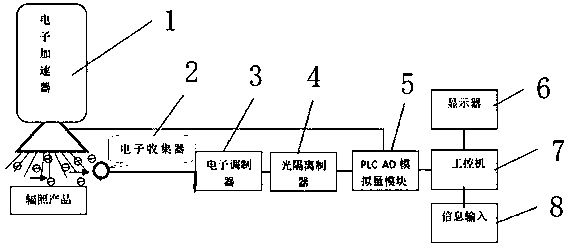
[0035] see figure 1 , figure 2 , image 3 It can be seen that a feedback control method for an irradiation system of an electron accelerator 1 according to the present invention comprises the following steps:

[0036] (1) Use the electron collector 2 to irradiate the electron beam accelerated by the accelerator onto the product and the electron collector 2 arranged around the product, and collect the scattered electrons through the electron collector 2;

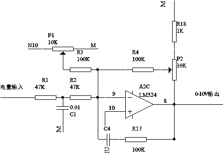
[0037] (2) The collected power is transmitted to the ML324 integrated module through the double-shielded radiation-resistant power transmission line 11 through the current-limiting resistor. After the current-limiting resistor limits the excessive power, it is amplified and adjusted by the ML324 integrated module to become a voltage signal of 0-10v ;The 0-10V voltage signal is adjusted by the LF353 integrated module and then input to ...


PUM


Abstract

The invention discloses a feedback control method and system for an electronic accelerator irradiation system. The control method includes steps that (1), electrons are collected by an electron collector; (2), the aggregated power is amplified and adjusted to become a voltage signal of 0-10v; (3), an electron beam of 0-60mA outputted by an electron accelerator is proportionally adjusted to correspond to the 0-10v voltage signal; (4), the 0-10v voltage signal is transmitted to an industrial computer through a PLC AD analog module; and (5), the digital signal is calibrated and compared by the industrial computer, and equipment is controlled. The electronic collector of the control system is electrically connected with an electronic modulator through a power transmission line and a current limiting resistor, the electronic modulator is electrically connected with the PLC AD analog module through an optical isolator, and the PLC AD analog module is electrically connected with a PLC and theelectron accelerator. The method and the system are advantaged in that beam intensity can be accurately monitored and controlled, and stability and accuracy of the quality of irradiated products canbe greatly improved.

Description

technical field [0001] The invention relates to a control method and system of an electron accelerator, in particular to a feedback control method and system of an irradiation system of an electron accelerator. Background technique [0002] 1. Radiation processing refers to the transfer of the energy of electron beams produced by electron accelerators (0.2MeV~10MeV) or gamma rays produced by radioactive isotopes (Cs-137 or Co-60) to irradiated substances. On the irradiated matter, ionization and excitation are generated to release orbital electrons to form free radicals. By controlling the radiation conditions, the physical properties and chemical composition of the irradiated material can be changed to form a new material that people need, or the organisms (microorganisms, etc.) can be irreversibly lost and damaged, to achieve goals that people want. This new processing technology is called radiation processing technology. For example, grafting, polymerization, fission o...

Claims


Application Information

Patent Timeline
IPC IPC(8): G21K5/00
CPCG21K5/00
Inventor 房春
Owner 房春
Learn More