
Heat dissipation type transformer

A transformer and heat dissipation technology, which is applied in the field of transformers, can solve the problems of shortening the service life of coils, high heat generation of transformers, poor heat dissipation of transformers, etc., and achieve the effects of prolonging service life, high safety in use, and high heat dissipation efficiency

Inactive Publication Date: 2019-02-15
四川星脉电子科技有限责任公司
View PDF0 Cites 6 Cited by
  • Summary
  • Abstract
  • Description
  • Claims
  • Application Information

AI Technical Summary

Problems solved by technology

[0002] Transformer is a device that uses the principle of electromagnetic induction to change AC voltage. The main components are primary coil, secondary coil and iron core (magnetic core), which can be used for terminal power supply and ring network power supply. The conversion is very convenient and ensures the reliability of power supply. and flexibility, but the transformer generates a lot of heat during work, so it needs to be equipped with corresponding heat dissipation equipment
[0003] Existing transformers are affected by the high temperature environment, and it is easy to convert electric energy into heat energy too much, causing unnecessary losses. If the temperature of the transformer is too high, it will be unfavorable to the coil of the transformer, which will easily cause the coil to age and shorten the service life of the coil; at the same time, the transformer Poor heat dissipation, resulting in excessively high iron core temperature, which may cause fire hazards

Method used


Image

  • Heat dissipation type transformer
  • Heat dissipation type transformer

Examples


Embodiment Construction

[0023] The present invention will be further described in detail below in conjunction with the accompanying drawings, so that those skilled in the art can implement it with reference to the description.

[0024] It should be understood that terms such as "having", "comprising" and "including" as used herein do not entail the presence or addition of one or more other elements or combinations thereof.

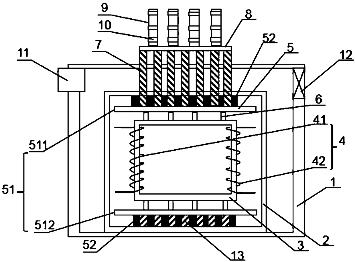
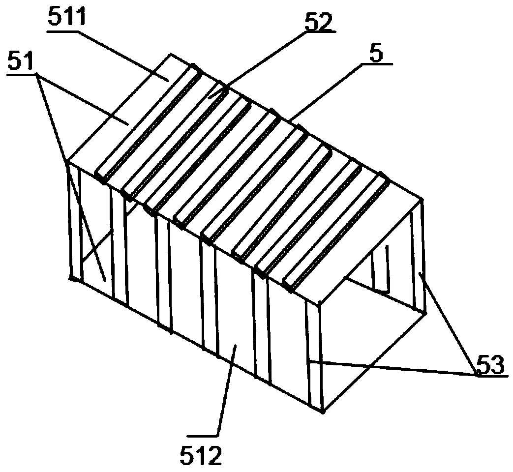
[0025] Such as Figure 1-2 Shown: a kind of radiator type transformer of the present invention, comprises:

[0026] Transformer housing 1;

[0027] Transformer body 2, which is installed on the transformer housing 1; the transformer body 2 includes an iron core 3, and a coil 4 wound on the iron core, and the periphery of the coil 4 and the iron core 3 are provided with matching The heat absorbing plate 5 includes two sets of panels 51 and a plurality of heat absorbing strips 53 connecting the two sets of panels 51 , and the inner surfaces of the two sets of panels 51 are provid...


PUM


Abstract

The invention discloses a heat dissipation type transformer. The transformer comprises a transformer housing and a transformer body mounted on the transformer housing; the transformer body comprises acore and a coil, a heat absorbing plate is arranged on the periphery of the coil and the core, and the heat adsorbing plate comprises two sets of panels, a plurality of heat absorbing strips and a plurality of heat absorbing tubes disposed on the inner side surfaces of the two groups of panels; a plurality of protrusions are respectively arranged on the outer side surfaces of the two groups of panels, and each of the protrusions is in contact with the transformer body; heat-conducting pipes are arranged on the upper portions of upper panels of the two groups of panels, the ends of each heat-conducting pipe extend upwardly to from the transformer body and the transformer housing, and are exposed in the external environment, heat dissipation plates are connected to the exposed portions, a plurality of heat-dissipating plates are arranged thereon, and a plurality of heat dissipation ribs wind around each of the heat-dissipating plates; the lower ends of the lower panels located on the two sets of panels are provided with fixing blocks, and the bottoms of each of the fixing blocks are fixed on the transformer body. The transformer has simple structure, and achieves a process of heat absorption, heat conduction and heat dissipation so as to achieve the characteristic of high heat dissipation efficiency.

Description

technical field [0001] The invention belongs to the technical field of transformers, and more specifically, the invention relates to a heat dissipation transformer. Background technique [0002] Transformer is a device that uses the principle of electromagnetic induction to change AC voltage. The main components are primary coil, secondary coil and iron core (magnetic core), which can be used for terminal power supply and ring network power supply. The conversion is very convenient and ensures the reliability of power supply. And flexibility, but the transformer generates a lot of heat during work, so it needs to be equipped with corresponding heat dissipation equipment. [0003] Existing transformers are affected by the high temperature environment, and it is easy to convert electric energy into heat energy too much, causing unnecessary losses. If the temperature of the transformer is too high, it will be unfavorable to the coil of the transformer, which will easily cause t...

Claims


Application Information

Patent Timeline
Patent Type & Authority Applications(China)
IPC IPC(8): H01F27/02H01F27/08H01F27/22
CPCH01F27/22H01F27/025H01F27/08H01F27/085
Inventor 袁红波
Owner 四川星脉电子科技有限责任公司
Learn More