Direct-current charging gun of new energy electric automobile

An electric vehicle, DC charging technology, applied in the direction of electric vehicle charging technology, electric vehicles, charging stations, etc., can solve the problems of not installing a temperature monitoring device, not being able to completely prevent live plugging, and damage to the electrical components of the gun body, etc., to achieve convenience The effects of positive connection, labor-saving grasping, and improved safety

Pending Publication Date: 2019-02-15
常州中电新能电器科技有限公司
View PDF0 Cites 13 Cited by
  • Summary
  • Abstract
  • Description
  • Claims
  • Application Information

AI Technical Summary

Problems solved by technology

In DC charging, the charging current of the DC charging gun is relatively large (generally greater than 100A), which is prone to safety accidents. Therefore, the user’s live plugging operation during the charging process must be absolutely prohibited. The release sequence of the inner long and short pins prevents the user from live plugging and unplugging. However, in actual use, due to the different plugging speeds of users, this method cannot completely eliminate the phenomenon of live plugging and unplugging.
[0004] In addition, the shells of the existing DC charging guns are all composed of splicing. The overall strength of the charging gun is low, and the waterproof performance is also poor. Cause damage, and, due to the intrusion of rainwater, the charging gun has a greater safety hazard in use
There is generally no temperature monitoring device inside the existing charging gun, and the charging current is large, and a large amount of heat will be generated during charging. The heat in the gun charging is monitored, and the existing charging gun cannot do this.

Method used


Image

  • Direct-current charging gun of new energy electric automobile
  • Direct-current charging gun of new energy electric automobile
  • Direct-current charging gun of new energy electric automobile

Examples


Embodiment 1

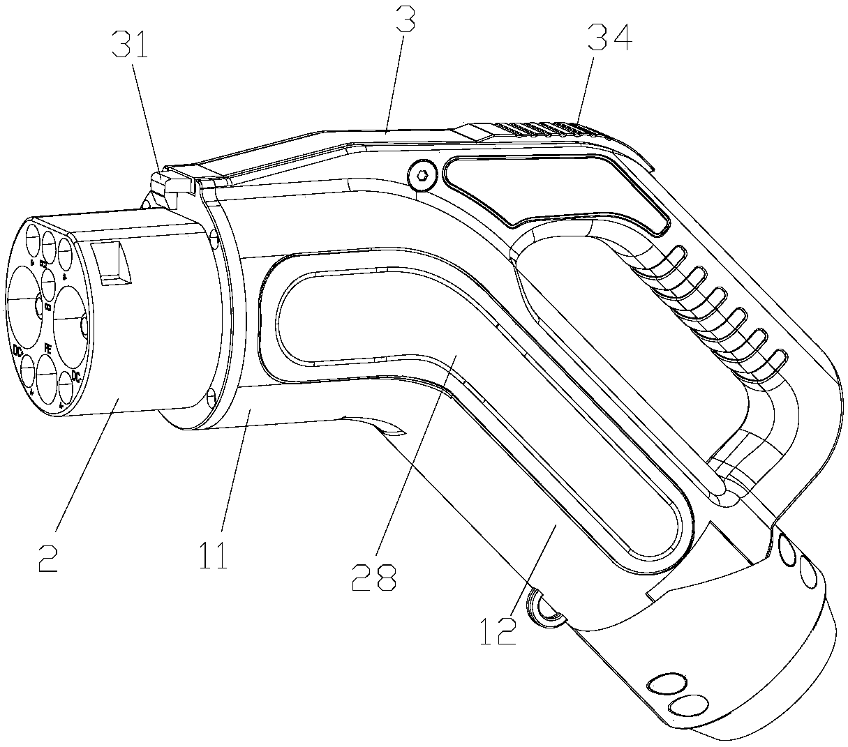
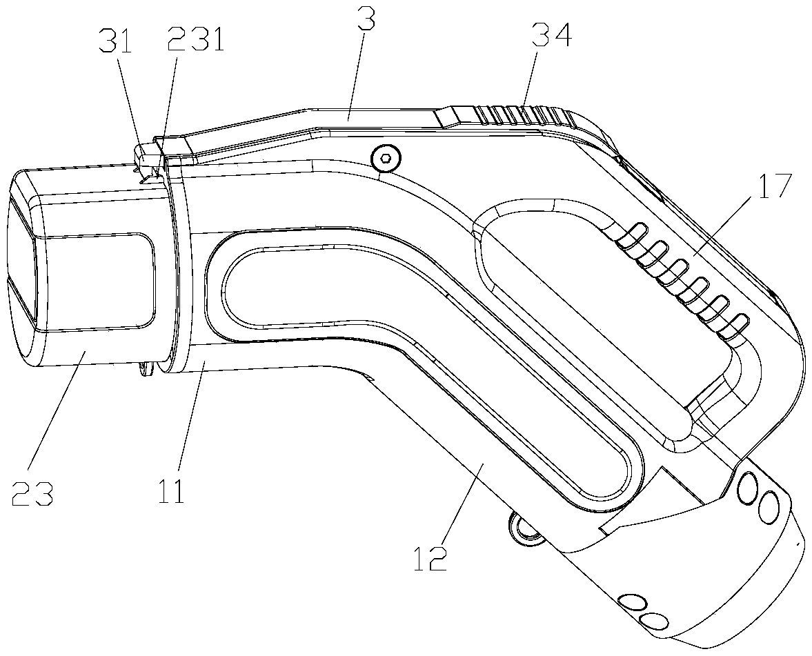
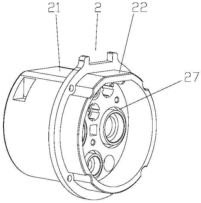
[0043] Embodiment 1: refer to Figure 1-Figure 16 , a DC charging gun for new energy electric vehicles, including a gun body 1, a charging plug 2 at the front end of the gun body 1, and a locking plate 3. The gun body is an integral injection molding structure, and the charging plug 2 is provided with a charging pin 25. The front end of 1 is the plug part 11 connected with the charging plug 2, the rear end of the gun body 1 is the connection part 12 connected with the cable, the plug part 11 is parallel to the horizontal line, and the connection part 12 is smooth from the rear end of the plug part 11 to the The rear lower side extends, the connecting part 12 and the plug part 11 form an obtuse angle of 130°, the length of the connecting part 12 is greater than the length of the plug part, and the longer length of the connecting part 12 provides sufficient space for the connection between the cable and the charging plug circuit board module Space, easy to connect, in addition, ...

Embodiment 2

[0049] Embodiment 2: The difference between this embodiment and Embodiment 1 is: in this embodiment, refer to Figure 17 , the outer wall surface of the waterproof rear ring 92 of the gun tail is a tapered surface structure, and the larger end of the tapered surface structure faces the side of the waterproof front ring of the gun tail, and contacts the cable holder through the tapered surface. After fixing, the cable holder and the gun The extrusion of the rear waterproof ring of the tail is stronger, which enhances the pressure between the waterproof rear ring of the gun tail and the cable, thereby improving the sealing performance of the place and improving the waterproof performance.

Embodiment 3

[0050] Embodiment 3: The difference between this embodiment and Embodiment 1 is: in this embodiment, refer to Figure 18 , the front end of the gun head waterproof ring 4 is provided with an annular protrusion 41 embedded in the step surface fit, the cross section of the annular protrusion 41 is an isosceles trapezoid, and the smaller end of the annular protrusion 41 is connected to the front end of the gun head waterproof ring , after the charging plug is connected to the plug part, the waterproof ring 4 of the tip of the gun will lean against the joint surface to further seal the joint surface and improve the waterproof effect. Cooperating with the groove, the annular protrusion 41 seals the joint surface of the waterproof ring 4 of the gun head and the charging plug. sex, tightness,


PUM


Abstract

The invention relates to the technical field of electric vehicle charging guns, and particularly relates to a direct-current charging gun of a new energy electric automobile; the direct-current charging gun comprises a gun body, a charging plug and a locking plate, wherein a charging contact pin is arranged in the charging plug; the gun body is of an integrated forming structure, and an inner cavity is formed in the gun body; an assembling cavity which is independent from the inner cavity and is not communicated with the inner cavity is formed in the upper part of the gun body; the locking plate is movably arranged at the opening of the assembling cavity; a detection assembly is arranged at the bottom of the locking plate in the assembling cavity; a sealing shell is arranged outside the detection assembly; a contact pin fixing base for fixing the contact pin is arranged in the charging plug, and a contact pin fixing hole is formed in the contact pin fixing base; a temperature monitoring hole is formed in the edge side of the contact pin fixing hole; a temperature monitoring device for monitoring the temperature in the position of the charging contact pin is arranged in the temperature monitoring hole; the temperature monitoring hole is poured and sealed with glue; the structure strength, the protection level and the safety performance of the charging gun are high, so that electrified operation of a user can be avoided; and the structure of the gun body conforms to the human engineering design, the grabbing is convenient and labor-saving, and the charging operation is facilitated.

Description

technical field [0001] The invention relates to the technical field of charging guns for new energy vehicles, in particular to DC charging guns for new energy electric vehicles. Background technique [0002] New energy electric vehicles refer to vehicles that use electricity as energy and are driven by electric motors. The exhaust emissions of new energy electric vehicles are zero. With the policy support and car purchase subsidies for new energy vehicles at home and abroad, the promotion and popularization of new energy vehicles have already It has become an inevitable trend, and supporting equipment such as charging guns related to new energy vehicles are also receiving more and more attention from manufacturers. [0003] At present, the charging methods of new energy electric vehicles are divided into DC charging and AC charging. The charging of new energy electric vehicles requires the use of charging guns. In DC charging, the charging current of the DC charging gun is ...

Claims


Application Information

Patent Timeline
Patent Type & Authority Applications(China)
IPC IPC(8): H01R13/502H01R13/52H01R13/58H01R13/627H01R13/629H01R13/631H01R13/66H01R13/70B60L53/16
CPCH01R13/502H01R13/52H01R13/5202H01R13/5205H01R13/5216H01R13/5227H01R13/5812H01R13/6275H01R13/629H01R13/631H01R13/6633H01R13/6683H01R13/70H01R2201/26Y02T10/70Y02T10/7072Y02T90/14
Inventor 叶敏舟刘博学叶文
Owner 常州中电新能电器科技有限公司
Why Eureka
Try Eureka