Probe structure of breast ultrasonic computed tomography structure

A tomography and ultrasound technology, applied in the field of medical equipment, can solve problems such as sealing problems, large water tank volume, waste of water resources, etc., and achieve the effects of easy operation, less water change, and resource saving.

Inactive Publication Date: 2019-02-19
WUHAN WESEE MEDICAL IMAGING CO LTD
View PDF7 Cites 5 Cited by
  • Summary
  • Abstract
  • Description
  • Claims
  • Application Information

AI Technical Summary

Problems solved by technology

Ultrasound imaging examination requires human tissue or animal tissue (such as breast, limbs, abdomen) to be immersed in water, and the annular ultrasonic probe is also in the water, moving up and down around the human tissue and scanning. In the prior art, the breast ultrasound tomography system During the examination, a person needs to lie down on the breast and dip it into the water. The ring-shaped ultrasonic probe is also in the water, moving up and down around the breast tissue and scanning. In the water, there is a sealing problem during the movement of the probe, and a large number of water changes are required during the examination. The water tank with a large volume is large in size and inconvenient to operate, resulting in a waste of water resources

Method used


Image

  • Probe structure of breast ultrasonic computed tomography structure
  • Probe structure of breast ultrasonic computed tomography structure
  • Probe structure of breast ultrasonic computed tomography structure

Examples


Embodiment Construction

[0029] In order to make the object, technical solution and advantages of the present invention clearer, the present invention will be further described in detail below in conjunction with the accompanying drawings and embodiments. It should be understood that the specific embodiments described here are only used to explain the present invention, not to limit the present invention.

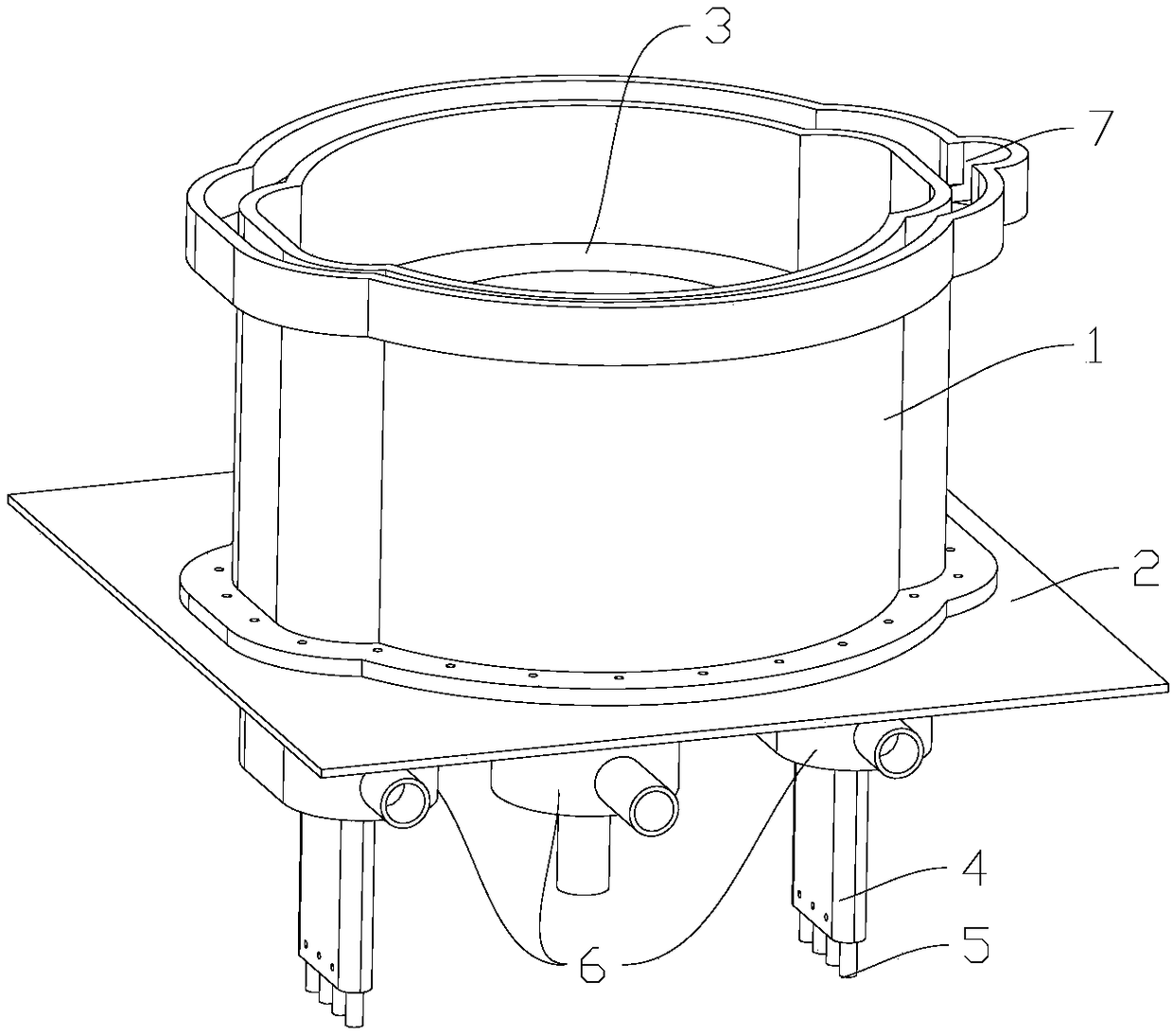
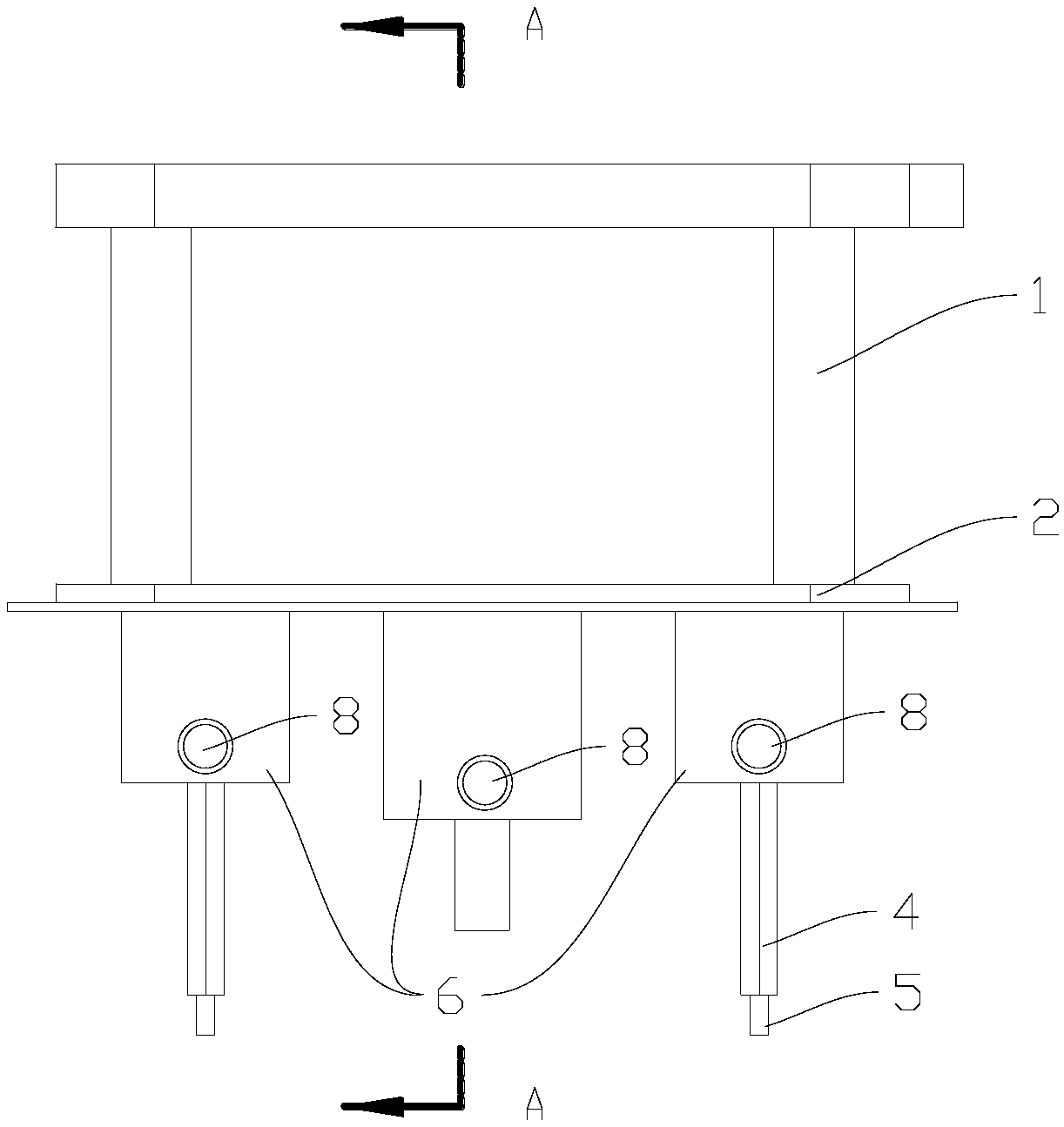
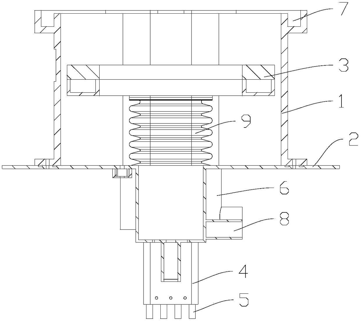
[0030] see Figure 1 to Figure 7 , a probe structure of a breast ultrasound tomography system, comprising:

[0031] The water tank has a water tank wall 1 and a water tank bottom 2, forming an accommodation space with an opening;

[0032] The probe 3 is arranged in the containing space; and

[0033] The driving mechanism 4 is arranged in the accommodation space, one end is connected to the probe 3, and the other end extends out of the bottom of the water tank 2 and is connected to the synchronous motor, so that the probe 3 is driven to move linearly in the accommodation space under the drive of t...


PUM


Abstract

The invention relates to a probe structure of a breast ultrasonic computed tomography structure. The probe structure of the breast ultrasonic computed tomography structure comprises a water tank, a probe and a driving mechanism, wherein the water tank is composed of a water tank wall and a water tank bottom, which encloses an accommodating space with an opening; the probe is arranged inside the accommodating space; the driving mechanism is arranged inside the accommodating space, one end of the driving mechanism is connected with the probe, the other end of the driving mechanism extends out ofthe water tank bottom and is connected with a synchronizing motor so that the driving mechanism can drive the probe through the synchronizing motor to move linearly inside the accommodating space. The probe structure of the breast ultrasonic computed tomography structure also comprises an elastic element arranged in a sleeve mode outside the driving mechanism, one end of the elastic element is connected to the probe, and the other end of the elastic element is connected to the water tank bottom to form an isolating space for isolating the driving mechanism and the isolating space. The probe structure of the breast ultrasonic computed tomography structure solves the problem of sealing during probe movement, and meanwhile due to the fact that a water container is small in water capacity andfurther low in water changing volume when patients change, saves resources and shortens time required for water change. Besides, the probe structure of the breast ultrasonic computed tomography structure is reasonable in space utilization, compact and exquisite in structure and convenient to operate.

Description

technical field [0001] The invention relates to the field of medical appliances, in particular to a probe structure of a mammary gland ultrasonic tomographic imaging system. Background technique [0002] An ultrasonic probe is a device that emits and receives ultrasonic waves during ultrasonic testing. The performance of the probe directly affects the characteristics of the ultrasonic wave and affects the detection performance of the ultrasonic wave. Ultrasound imaging examination requires human tissue or animal tissue (such as breast, limbs, abdomen) to be immersed in water, and the annular ultrasonic probe is also in the water, moving up and down around the human tissue and scanning. In the prior art, the breast ultrasound tomography system During the examination, a person needs to lie down on the breast and dip it into the water. The ring-shaped ultrasonic probe is also in the water, moving up and down around the breast tissue and scanning. In the water, there is a seali...

Claims


Application Information

Patent Timeline
Patent Type & Authority Applications(China)
IPC IPC(8): A61B8/00A61B8/08
CPCA61B8/0825A61B8/4444
Inventor 倪举鹏丁明跃尉迟明
Owner WUHAN WESEE MEDICAL IMAGING CO LTD
Why Eureka
Try Eureka