High-pressure jet-flow nozzle and high-pressure jet-flow crushing device using same

A high-pressure jet and nozzle technology, applied in grain processing and other directions, can solve the problems of increasing the particle size distribution of materials, affecting the pulverization effect, and damaging the components of the jet flow channel, so as to enhance the sealing effect and achieve the effect of expanding production capacity.

Pending Publication Date: 2019-02-19
北京协同创新食品科技有限公司
View PDF14 Cites 4 Cited by
  • Summary
  • Abstract
  • Description
  • Claims
  • Application Information

AI Technical Summary

Problems solved by technology

The pressure fluctuation will cause the flow velocity of the material in the jet flow path to fluctuate, thereby affecting the crushing effect and increasing the particle size distribution of the material
In addition, the pulse pressure fluctuation will also produce a large impact on the jet flow path components, so that there is also a risk of damage to the jet flow path components

Method used


Image

  • High-pressure jet-flow nozzle and high-pressure jet-flow crushing device using same
  • High-pressure jet-flow nozzle and high-pressure jet-flow crushing device using same
  • High-pressure jet-flow nozzle and high-pressure jet-flow crushing device using same

Examples


Embodiment 1

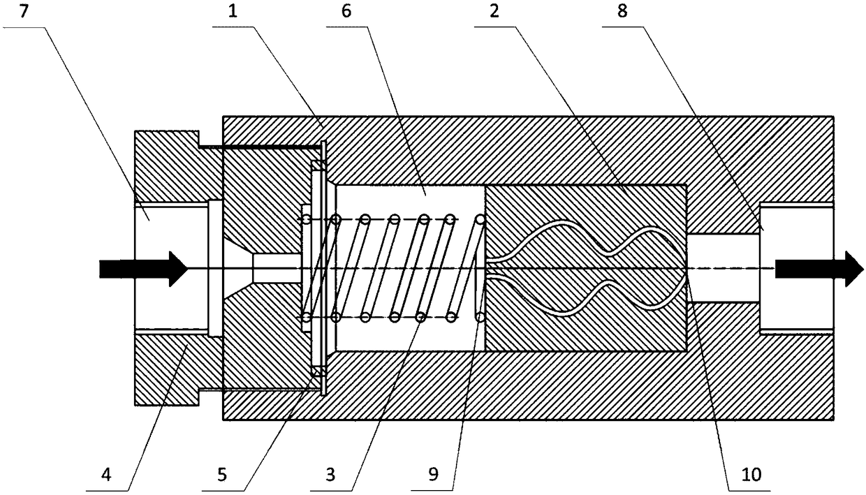
[0037] A high-pressure jet nozzle, such as figure 1As shown, it includes a stainless steel shell 1, a jet flow channel part 2, a stainless steel spring 3, a sealing cover 4, a sealing ring 5, and a buffer chamber 6. The sealing cover 4 is provided with a first liquid inlet 7, and one end of the housing 1 is provided with The first liquid outlet 8, the other end is fastened to the sealing cover 4, and the sealing ring 5 is arranged between the sealing cover 4 and the housing 1; the jet channel part 2 is arranged in the housing 1, and one end is provided with a second liquid inlet port 9, and the other end is provided with a second liquid outlet 10; the elastic component 3 is arranged between the jet flow path component 2 and the sealing cover 4, and the sealing cover 4 compresses the elastic component 3 when tightened, and the elastic component 3 compresses to generate elasticity The force fixes the jet channel part 2 and the housing 1; the buffer cavity 6 is formed by surround...

Embodiment 2

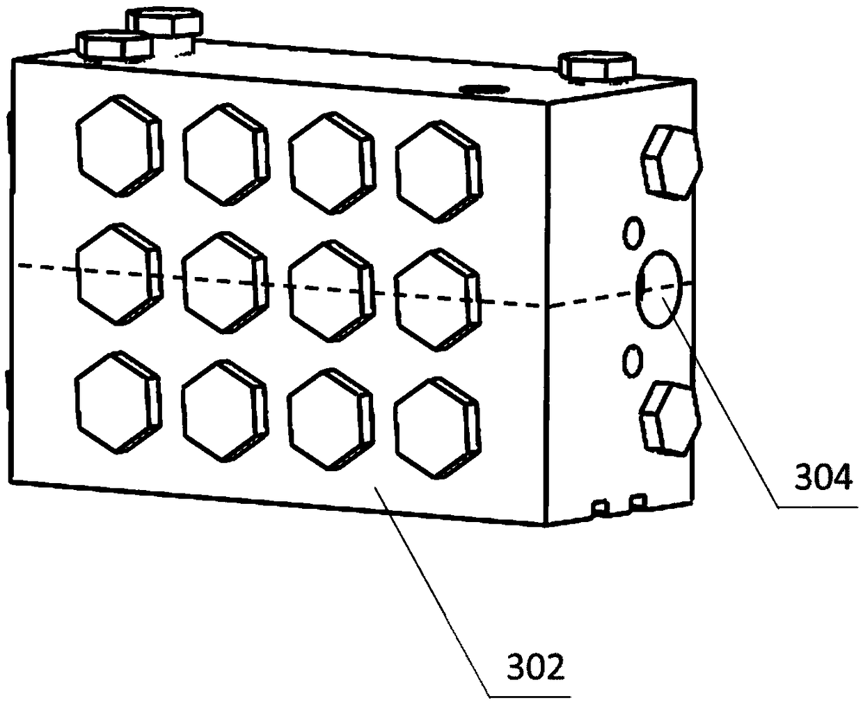
[0048] A high-pressure jet nozzle module, such as image 3 As shown, where the cross-sectional view is shown in Figure 4 shown. It includes a high-pressure jet nozzle structure 301 , an integrated housing 302 , a liquid inlet 303 , and a liquid outlet 304 . The structure of the high-pressure jet nozzle is basically the same as the high-pressure jet nozzle in Example 1, except that the position of the first liquid inlet is changed from being arranged on the sealing cover to being arranged on the side wall of the buffer chamber shell, and the buffer chambers are connected to each other. Unified feed from the liquid inlet 303. The first liquid outlets of each high-pressure jet nozzle structure are also communicated with each other.

[0049] It can be seen that, compared with the comparative example, Example 2 can conveniently realize the expansion of production capacity on the same overall structure.

[0050] When the high-pressure jet nozzle module of this embodiment is cru...

Embodiment 3

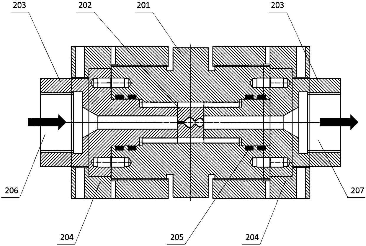
[0052] A high-pressure jet nozzle, such as Figure 5 shown. Compared with the high-pressure jet nozzle in Embodiment 1, it also includes two sets of sealing rings 11, one of which is arranged between the side wall of the jet flow path part 2 and the housing 1, and the other set is arranged on the side wall of the jet flow path part 2. Between the rear end face and the housing 1. The addition of two sets of sealing rings can better achieve sealing, and at the same time reduce the requirements for machining accuracy.


PUM


Abstract

The invention relates to a high-pressure jet-flow nozzle and a high-pressure jet-flow crushing device using the same. An elastic component is arranged between a jet-flow channel component and a sealing cover of the high-pressure jet-flow nozzle, and the jet-flow channel component is fixed to a shell. In addition, a buffering cavity is formed by a space used for accommodating the elastic component.Assembling of the high-pressure jet-flow nozzle can be simplified, and damage to the jet-flow channel component is avoided in the assembling process; sealing between the jet-flow channel component and the shell can be automatically achieved by means of the pressure generated by a high-pressure pump; the capacity can be conveniently improved; pressure fluctuation can be reduced through the buffering cavity, so that the crushing effect is improved, and particle size distribution of materials is decreased; and meanwhile, the impact of pressure fluctuation on the jet-flow channel component is reduced, and the damage risk of the jet-flow channel component is lowered.

Description

technical field [0001] The invention belongs to the technical field of pulverization, in particular to the jet pulverization technology applied to wet pulverization processing. Background technique [0002] The principle of high-pressure jet crushing is different from traditional crushing and grinding equipment. The rough pulp after rough grinding is first pressurized to the working pressure in the high-pressure jet mill, and then the pressurized coarse pulp passes through a specially designed channel structure. At this time, the coarse slurry flows at high speed in the channel, and the particles in the coarse slurry Under the high shear, collision and cavitation effects generated during the high-speed flow process, pulverization and refinement are realized. High-pressure jet pulverization technology can be applied in food, medicine, daily chemical, coating and other fields. Especially in the field of food processing, the dregs, grains and fiber components of food material...

Claims


Application Information

Patent Timeline
Patent Type & Authority Applications(China)
IPC IPC(8): B02C19/06
CPCB02C19/06
Inventor 周至富陈颖刘佳刘宇
Owner 北京协同创新食品科技有限公司
Why Eureka
Try Eureka