
Wind power generation power distribution cabinet surface paint spraying device

A technology for power distribution cabinets and paint, applied in the direction of spraying devices, etc., can solve problems such as large manpower consumption, adverse effects on workers' health, and inability to guarantee the spraying effect

Active Publication Date: 2019-02-19
CHONGQING WANGBIAN ELECTRIC GRP CORP
View PDF6 Cites 4 Cited by
  • Summary
  • Abstract
  • Description
  • Claims
  • Application Information

AI Technical Summary

Problems solved by technology

However, the existing painting device can only spray paint on one of the surfaces of the distribution cabinet when painting, and it is necessary to artificially rotate the distribution cabinet to spray paint on the other surface after one surface is sprayed.
During the turning process, on the one hand, it takes a lot of manpower and is inefficient; on the other hand, the workers will inhale a large amount of paint mist when turning, which will have an adverse effect on the workers' health
In addition, the current spraying device cannot guarantee the uniformity of the spraying effect

Method used


Image

  • Wind power generation power distribution cabinet surface paint spraying device
  • Wind power generation power distribution cabinet surface paint spraying device
  • Wind power generation power distribution cabinet surface paint spraying device

Examples


Embodiment Construction

[0019] The following is further described in detail through specific implementation methods:

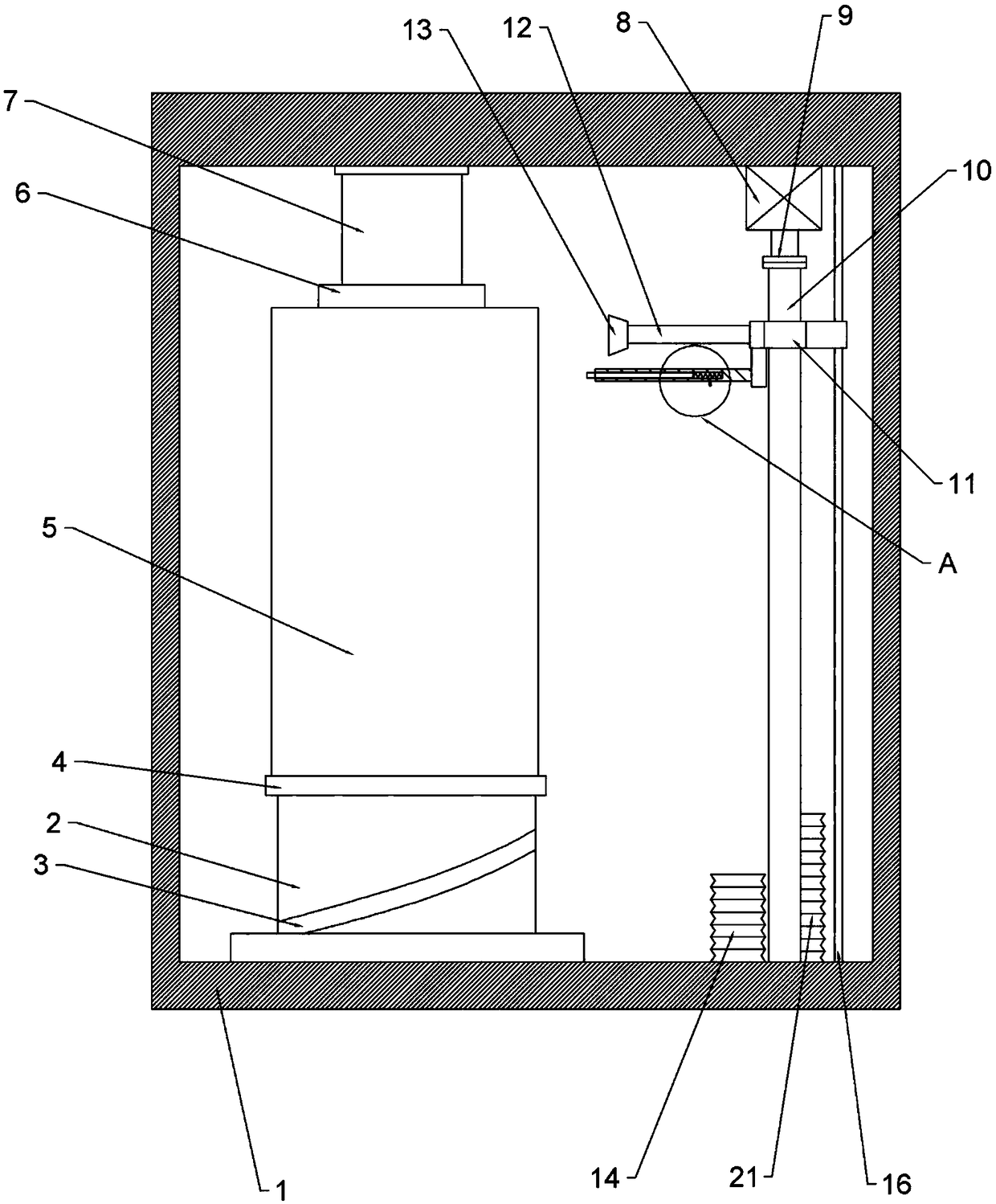
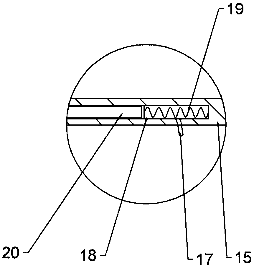
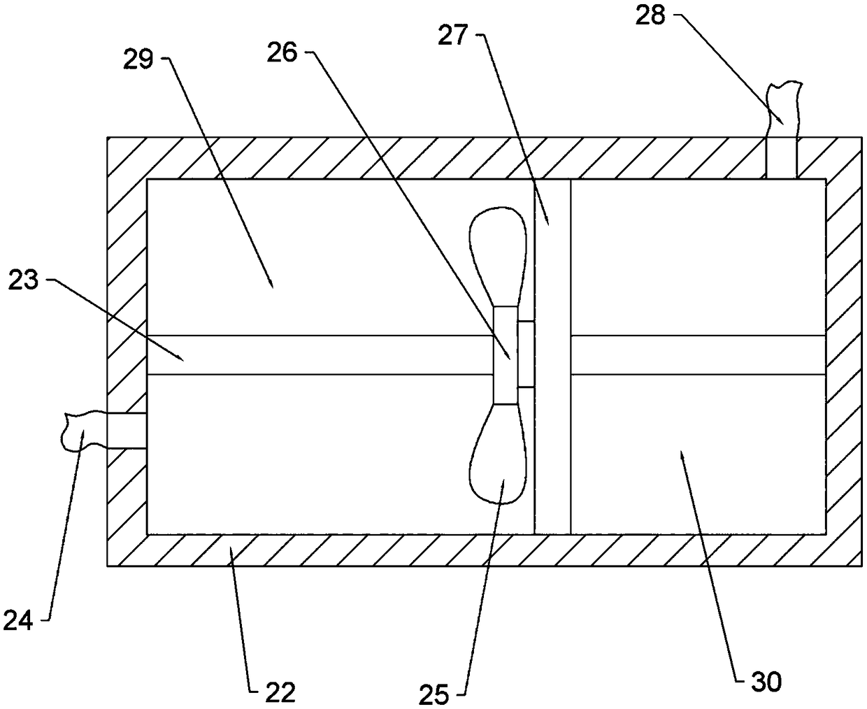
[0020] The reference signs in the drawings of the specification include: housing 1, drum 2, chute 3, turntable 4, power distribution cabinet 5, pressure plate 6, hydraulic cylinder 7, motor 8, coupling 9, screw 10, screw thread Part 11, connecting rod 12, nozzle 13, first elastic bellows 14, outer rod 15, guide rod 16, air pipe 17, cavity 18, spring 19, pole 20, second elastic bellows 21, paint storage bin 22 , Transverse shaft 23, connecting pipe 24, stirring blade 25, ring 26, slide plate 27, connecting pipe 28, paint chamber 29, air chamber 30.

[0021] The embodiment is basically as attached figure 1 and figure 2 Shown: a surface painting device for a wind power distribution cabinet, including a housing 1, a rotating cylinder 2, a one-way bearing and a turntable 4 for placing a distribution cabinet 5. One side of the casing 1 is provided with a door and a closing plate for cl...


PUM


Abstract

The invention belongs to the field of paint spraying devices, and particularly discloses a wind power generation power distribution cabinet surface paint spraying device. The wind power generation power distribution cabinet surface paint spraying device comprises a shell, a rotation barrel, a one-way bearing and a rotation disc. The lower end of the rotation barrel is rotationally connected with the bottom of the shell, and the upper end of the rotation barrel is connected with the rotation disc through the one-way bearing. The shell is internally provided with a paint spraying structure and amoving structure. The paint spraying structure comprises a paint storage bin, a communication pipe and a sprayer, and the two ends of the communication pipe are connected with the paint storage bin and the sprayer correspondingly. The moving structure comprises a power source, a screw and a threaded piece, wherein the power source is fixedly connected with the shell, the screw is vertically arranged, an output shaft of the power source is connected with one end of the screw, the other end of the screw is rotationally connected with the shell, the threaded piece and the screw are in threaded fit, a guide rod parallel to the screw is arranged in the shell, and the guide rod is in sliding fit with the threaded piece. The sprayer is fixedly connected with the threaded piece. The 1 / 4 circumference face of the rotation barrel is provided with a chute, and the threaded piece is provided with a lifting lever capable of being inserted in the chute. The device can achieve automatic power distribution cabinet paint spraying, and paint spraying is uniform.

Description

technical field [0001] The invention belongs to the field of painting devices, and specifically discloses a surface painting device of a wind power distribution cabinet. Background technique [0002] Wind power refers to converting the kinetic energy of wind into electrical energy. Wind is a non-polluting energy source. Using wind power to generate electricity is very environmentally friendly and can generate huge amounts of electricity. Therefore, more and more countries pay more attention to wind power generation. [0003] The power distribution cabinet is the final equipment of the power distribution system. It is the general name of the motor control center. Load, this level of equipment should provide protection, monitoring and control of the load. [0004] Power distribution cabinets need to be placed outside for a long time, and wind power distribution cabinets are mostly placed in outdoor places with strong winds, and these places are generally places with strong w...

Claims


Application Information

Patent Timeline
IPC IPC(8): B05B13/02B05B13/04B05B15/25
CPCB05B13/0228B05B13/041B05B15/25
Inventor 皮统政邹红徐帮恒徐进毛国红潘尚义
Owner CHONGQING WANGBIAN ELECTRIC GRP CORP
Learn More