Laser drilling control method

A control method and laser drilling technology, applied in laser welding equipment, manufacturing tools, welding equipment and other directions, can solve the problems of affecting processing, non-linkage, difficult to cut or form notches, etc., to improve processing efficiency and reduce control time. , the effect of smooth section

Active Publication Date: 2019-02-19
SHENZHEN JIXIANGYUN TECH CO LTD
View PDF9 Cites 10 Cited by
  • Summary
  • Abstract
  • Description
  • Claims
  • Application Information

AI Technical Summary

Problems solved by technology

[0016] A. There will be traces of the knife on the edge of the step on each floor. This kind of trace will easily make it difficult to cut or form a notch, which will not only cause the anchorage to fail to fall off naturally, but also affect the processing of the subsequent process;
[0017] B. Since the 3D vibrating mirror is used, the movement efficiency and processing mode will be faster than the existing technology 1 and 2, but because the Z and XY axes of the vibrating mirror are not linked, the processing efficiency still cannot reach the best ideal state

Method used


Image

  • Laser drilling control method
  • Laser drilling control method
  • Laser drilling control method

Examples


Embodiment Construction

[0038] The present invention will be described in further detail below with reference to the accompanying drawings and embodiments.

[0039] The hardware basis of the present invention:

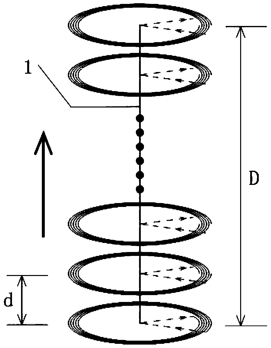
[0040] 1. The processing object of the present invention is especially suitable for transparent and fragile solid materials, such as ordinary untempered glass drilling, high-purity quartz drilling, solar antireflection and hard glass drilling, etc. The control method of the present invention revolves around processing such materials;

[0041] 2. The present invention needs to use a low-pulse-width green laser or an ultraviolet laser as the light source for processing. After setting appropriate laser parameters, the laser can directly vaporize the raw materials near the focus;

[0042] 3. The present invention needs to use a 3D galvanometer as a scanning tool.

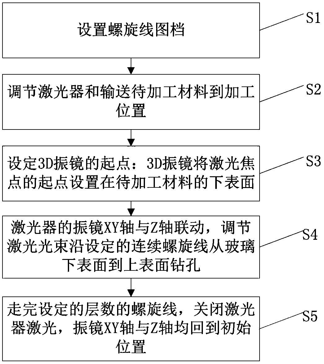
[0043] like figure 2 As shown, the present invention comprises the following steps:

[0044] S1: Set the spiral line file: set t...


PUM

PropertyMeasurementUnit
thicknessaaaaaaaaaa
transmittivityaaaaaaaaaa

Abstract

The invention provides a laser drilling control method and belongs to the field of laser processing. The laser drilling control method comprises the following steps: arranging spiral line drawing archives; adjusting a laser and conveying a to-be-processed product to a processing position; setting the starting point of a 3D vibrating mirror, wherein the 3D vibrating mirror sets the starting point of the laser focal point on the lower surface of the to-be-processed product; linking the XY axis and Z axis of the vibrating mirror of the laser, and adjusting the laser beam to drill from the lower surface to the upper surface of glass along the set continuous spiral line; and travelling on the entire spiral line with set layers, turning off the laser, and enabling the XY axis and Z axis of the vibrating mirror to return to the initial position. The laser drilling control method has the following benefits: the processing efficiency is improved, a connecting knife edge for turning on and off laser is not formed from bottom up, and the fracture surface is smooth.

Description

technical field [0001] The invention relates to a display screen structure, in particular to a laser drilling control method. Background technique [0002] With the development of production and transportation fields toward higher and higher speed and higher precision, many fields have higher requirements for the speed and accuracy of conveying materials. [0003] Especially in the rapidly developing machinery and equipment industry and the subdivisions of the logistics industry, the desire for high-precision, high-speed, and high-speed transportation is rushing. [0004] At present, the mainstream product in the market is low-iron tempered suede glass with a thickness of 3.2mm. In the corresponding wavelength range of the solar cell spectrum (320-1100nm), the light transmittance can reach more than 91%. Reflectivity. The suede is specially embossed, which is made by pressing a special pyramid pattern on the glass surface. However, the pattern of the suede will cause the ...

Claims


Application Information

Patent Timeline
Patent Type & Authority Applications(China)
IPC IPC(8): B23K26/382B23K26/082
CPCB23K26/082B23K26/382
Inventor 胡柳平朱宇军冯建华黄再福
Owner SHENZHEN JIXIANGYUN TECH CO LTD
Why Eureka
Try Eureka