Supercharge Your Innovation With Domain-Expert AI Agents!

Sufficient cooling and sealing structure of electric spindle

A sealing structure, motorized spindle technology, applied in the direction of engine sealing, large fixed members, maintenance and safety accessories, etc., can solve the problem of dustproof and cooling sealing relying on a sealing ring to achieve, cooling and sealing effects need to be improved and improved, sealing and dust-proof effect, to achieve the effect of excellent cooling effect, increased flow length, and guaranteed accuracy

Pending Publication Date: 2019-02-19
SHAANXI HALET PRECISION MACHINERY
View PDF0 Cites 1 Cited by
  • Summary
  • Abstract
  • Description
  • Claims
  • Application Information

AI Technical Summary

Problems solved by technology

Under the existing technology, the problems in the design of the cooling structure of the electric spindle are: 1. The cooling groove in the stator water jacket is designed as a linear through groove along the axial direction of the stator; the cooling area is limited; the cooling effect is not good; 3. Between the motor stator water jacket and the motor stator, a seal ring is used at the end of the motor stator shaft to achieve sealing; dustproof and cooling seals rely on a seal ring; once worn, the seal and waterproof The dust effect is affected at the same time; the frequency of fault maintenance is increased; the cooling and sealing effects need to be improved and improved

Method used


Image

  • Sufficient cooling and sealing structure of electric spindle
  • Sufficient cooling and sealing structure of electric spindle
  • Sufficient cooling and sealing structure of electric spindle

Examples


Embodiment Construction

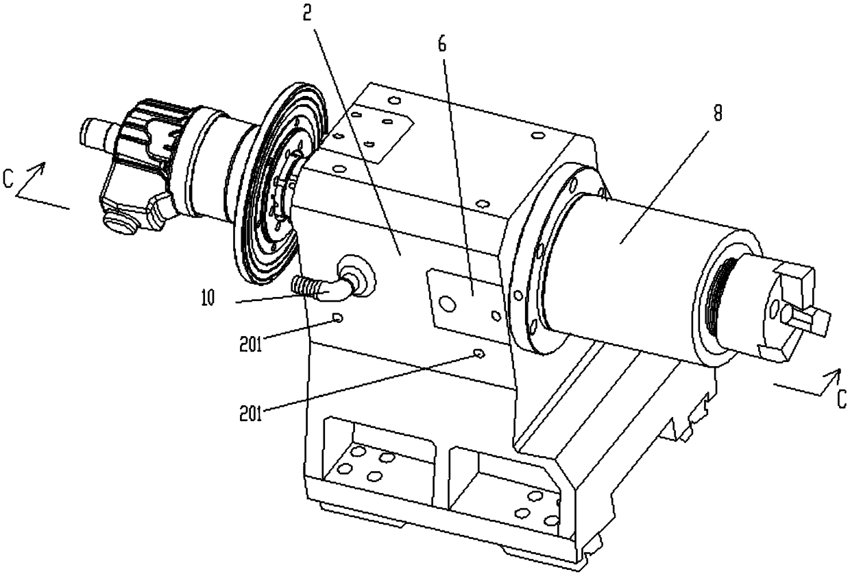
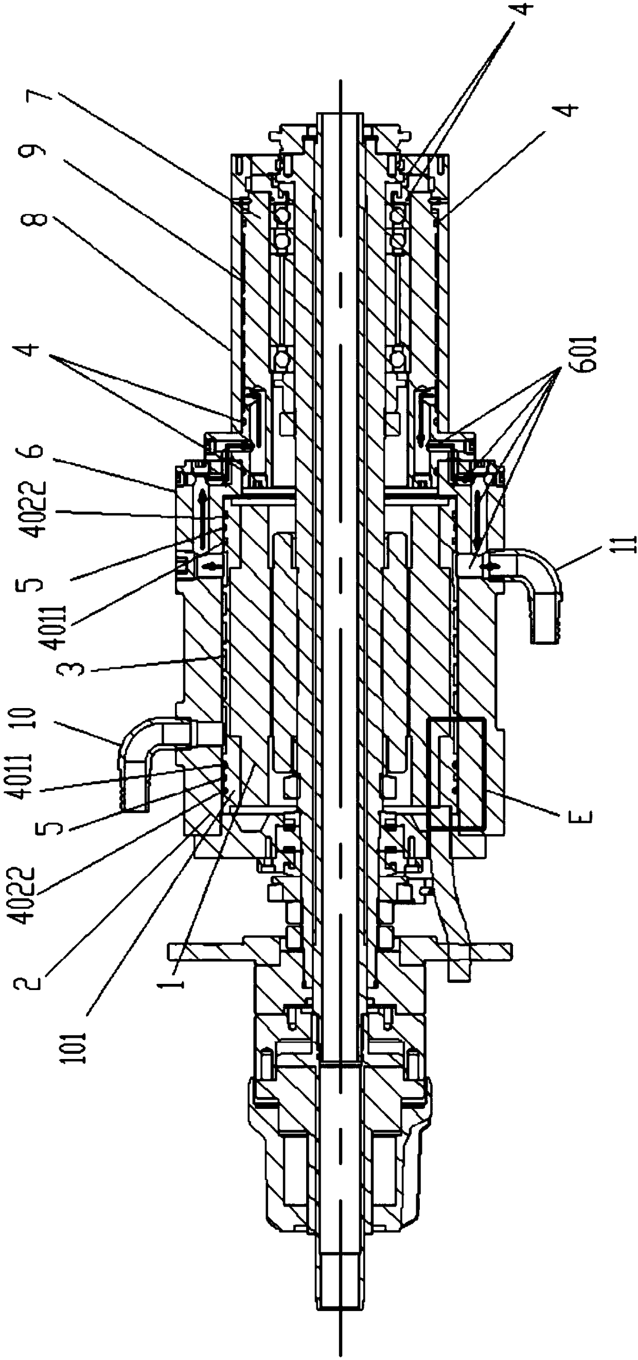
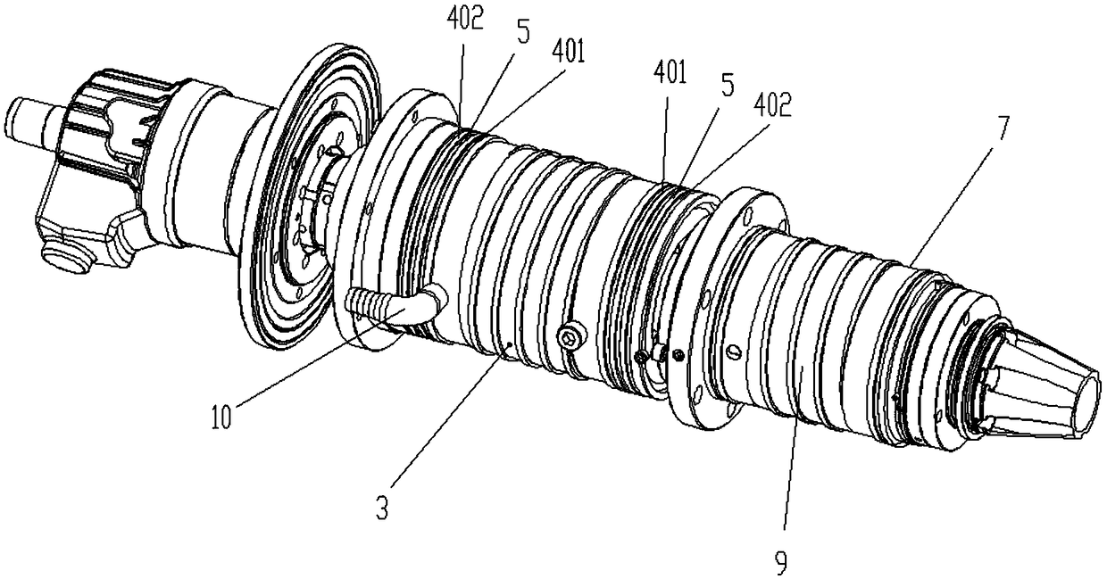
[0018] Attached below Figure 1-4 Specific examples of the present invention are described.

[0019] The following examples facilitate a better understanding of the present invention, but do not limit the present invention. The following embodiments are only some of the embodiments of the present invention, but not all of them. The components used in the following examples are commercially available unless otherwise specified.

[0020] In the description of the present invention, it should be noted that the terms "first" and "second" are used for description purposes only, and should not be understood as indicating or implying relative importance. The orientation or positional relationship indicated by the terms "center", "upper", "lower", "left", "right", "vertical", "horizontal", "inner", "outer" and the like are based on the The orientation or positional relationship is only for the convenience of describing the present invention and simplifying the description, but does...


PUM


Abstract

The invention provides a sufficient cooling and sealing structure of an electric spindle. A stator spiral fluid channel is cut on the outer cylinder face of a cylindrical shell of a motor stator; theouter sides of the two ends of the stator spiral fluid channel, namely the combination face of the shaft end of the cylindrical shell of the motor stator and the shaft end of a stator water jacket achieves double radial sealing of the water cooling shaft end of the motor stator through first radial limiting grooves, first sealing rings in the first radial limiting grooves, second radial limiting grooves parallel to the first radial limiting grooves and second sealing rings in the second radial limiting grooves; and radial water leaking grooves which are parallel to the first radial limiting grooves and the second radial limiting grooves and are spaced with the first radial limiting grooves and the second radial limiting grooves by a certain distance are manufactured between the first radial limiting grooves and the second radial limiting grooves for double radial sealing of the shaft end of the motor stator. The sufficient cooling and sealing structure is compact in structure, superior in cooling and dust isolation effect and good in sealing; cooling liquid obtained after leakage of a sealing ring can be discharged out of an electric spindle shell in time; the overall frequency ofthe electric spindle is reduced while heat generated by high-speed rotation of the electric spindle is sufficiently brought away; and the service life of the electric spindle is prolonged.

Description

technical field [0001] The invention belongs to the technical field of electric spindle cooling, and in particular relates to a sufficient cooling and sealing structure for an electric spindle. Background technique [0002] At present, the electric spindle is a new technology that integrates the machine tool spindle and the spindle motor in the field of CNC machine tools. It has the advantages of compact structure, light weight, small inertia, low noise and fast response. However, since the electric spindle integrates the motor into the spindle unit, the motor is built-in, the casing is closed, and the speed is very high, the heat generated by the power loss of the motor and the heat generated by the friction of the front and rear bearings cannot be discharged in time, resulting in the formation of complex internal electric spindle. The temperature field makes the thermal and dynamic characteristics of the electric spindle worse, thus affecting the normal operation of the e...

Claims


Application Information

Patent Timeline
IPC IPC(8): F16J15/06B23B19/02B23Q11/12
CPCF16J15/008F16J15/06B23Q1/70B23Q11/127
Inventor 周文斌吴小刚李会生
Owner SHAANXI HALET PRECISION MACHINERY
Features
  • R&D
  • Intellectual Property
  • Life Sciences
  • Materials
  • Tech Scout
  • Unparalleled Data Quality
  • Higher Quality Content
  • 60% Fewer Hallucinations
Learn More